
Actuator Connector CNC Machining
Estimate the routing risk for clevises, rod ends, eye brackets, flanges, and custom couplings before you send an RFQ. The result explains machining drivers, assumptions, boundaries, and the next action needed for a quote-ready connector print.
Why Connector Precision Matters
Connectors are the critical link between the actuator and the load. Misalignment or poor thread quality can induce side-loading on the cylinder, drastically reducing the lifespan of seals and bearings.
Thread integrity is critical for load transfer.
Actuator connectors transmit the full push/pull force of the system. Precise threading ensures load is distributed evenly, preventing premature stripping or fatigue failure under high cyclic loads.
Single-setup machining improves clevis alignment.
Machining the U-slot and cross-hole of a clevis in multiple setups introduces error. Mill-turn equipment allows us to machine these features relative to the main axis in one go.
Material selection impacts galling and wear.
Stainless steel connectors (like 17-4PH) are prone to thread galling (cold welding). Proper material hardness differentials and surface treatments mitigate this risk.
General tolerances are not enough for connector datums.
Untoleranced dimensions can follow a general tolerance standard, but load-bearing connector features still need drawing-level datums, true-position controls, and fit requirements.
Manufacturing Validation & Limits
Connector Capability Matrix
These routing bands are decision aids, not quote guarantees. They show what must be specified before a supplier can price actuator connector CNC machining reliably.
| Connector feature | Normal CNC route | Quote input needed | Boundary to watch |
|---|---|---|---|
| Clevis U-slot and cross-hole | 4-axis or 5-axis milling, drill/ream in one setup | Pin diameter, slot width, true position, parallelism | Long small-diameter holes can drift from tool deflection. |
| Threaded rod end | Mill-turn or CNC turning with thread milling/single point | Thread standard, class, engagement length, shoulder relief | Stainless threads need galling mitigation and gauge planning. |
| Flanged connector | Turning plus live-tool bolt pattern machining | Bolt circle, face flatness, perpendicularity, sealing face | Interrupted cuts on light flanges can drive chatter marks. |
| Custom coupling | Multi-axis mill-turn after interface definition | Torque/load case, spline/key/clamp details, datum scheme | No reliable estimate without a drawing-defined interface. |
Actuator Connector CNC Machining Visuals
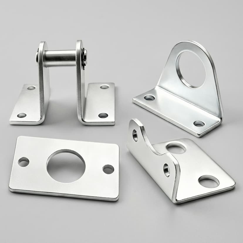
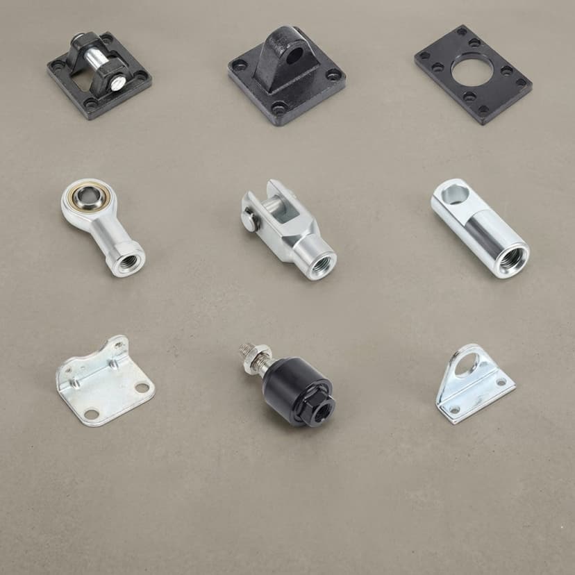
Representative connector, clevis, and mounting-interface images ground the actuator connector CNC machining discussion in the actual part families buyers compare before quoting.
Source Ledger & Evidence Limits
| Topic | Source | Date | Used for | Limit |
|---|---|---|---|---|
| Unified inch thread classes | ASME B1.1 official product page | Checked July 17, 2026 | Used as the source for thread form, series, class, allowance, tolerance, and designation references on inch threads. | Metric threads, proprietary actuator threads, and customer-specific thread notes require their own standard or print callout. |
| Untoleranced linear/angular dimensions | ISO 2768-1:1989 catalogue page | Checked July 17, 2026 | Used only for general tolerance context when a drawing leaves non-critical linear or angular dimensions untoleranced. | It does not replace explicit GD&T for clevis holes, datum features, thread axes, or bearing/pin fits. |
| Legacy geometrical general tolerances | ISO 2768-2:1989 catalogue page | Checked July 17, 2026 | Used as a warning because the ISO catalogue shows ISO 2768-2 with withdrawn styling. | Do not use it as the only authority for connector true position, concentricity, or perpendicularity on new prints. |
| Stainless-steel galling risk | British Stainless Steel Association galling note | Checked July 17, 2026 | Used for the statement that galling is adhesive wear/cold welding and is affected by stress, lubrication, design tolerance, surface finish, hardness, and microstructure. | Specific prevention must be validated against alloy pairing, surface treatment, preload, lubrication, and service temperature. |
| Shop capability envelope | Internal DFM rule set | Reviewed July 17, 2026 | Used for routing heuristics, lead-time bands, and the example +/-0.0127 mm critical-feature discussion. | The value is not a universal guarantee; final capability depends on feature size, datum access, material condition, and inspection method. |
Inspection & Quality Assurance Plan
| Inspection Point | Verification Step | Evidence Output | Risk Mitigated |
|---|---|---|---|
| Thread Gauge Inspection | Verify internal/external threads using calibrated Go/No-Go gauges per ASME B1.1. | Thread class compliance report (Class 2A/3A). | Loose threads cause backlash; tight threads cause binding and galling. |
| Cross-Hole Pin Fit | Measure the diameter and cylindrical form of clevis/eye holes using pin gauges or CMM. | Dimensional inspection log (±0.0127 mm precision). | Oversized holes cause sloppy linkages; undersized holes prevent pin insertion. |
| Concentricity Check | Assess concentricity of the connector head to the threaded shank using dial indicators or CMM. | Runout measurements report. | Eccentric connectors introduce side-loading on the actuator rod seals. |
Material Tradeoffs for Connector Machining
17-4PH stainless steel
- Best fit
- High strength plus corrosion resistance in compact load-path connectors.
- Tradeoff
- Higher tool wear, heat-treatment planning, and greater galling risk in threaded joints.
- Mitigation
- Define material condition, avoid stainless-on-stainless pairing when possible, and specify lubrication or surface treatment.
4140/4340 alloy steel
- Best fit
- Heavy-duty industrial force transfer with high cyclic loading.
- Tradeoff
- May require heat treatment, coating, or corrosion protection after machining.
- Mitigation
- Plan post-heat-treat inspection and protect critical fits during plating or coating.
6061/7075 aluminum
- Best fit
- Robotics and automation connectors where weight reduction matters.
- Tradeoff
- Lower thread wear resistance and possible bearing-surface damage if pin loads are high.
- Mitigation
- Use inserts, bushings, hardcoat anodize, or redesign load-bearing features.
Brass/bronze
- Best fit
- Low-friction bushings, non-sparking requirements, or moderate-load interfaces.
- Tradeoff
- Lower structural margin than steels for compact high-force rod ends.
- Mitigation
- Validate load rating and separate bushing functions from primary structural load paths.
Risk Matrix & Mitigation Path
The estimator is useful only when its limits stay visible. These are the risks most likely to create wrong sourcing, wrong drawings, or mismatched supplier quotes.
Misuse risk
Cost risk
Scenario mismatch
Evidence gap
Scenario Outcomes
Low-volume stainless clevis
Aluminum robotic rod end
Production flanged connector
RFQ Checklist
- 2D drawing with datums, GD&T, thread class, pin fit, and acceptance criteria
- 3D CAD model in STEP or native format
- Material grade, condition, heat treatment, and finish/plating requirements
- Prototype, pilot, and annual production quantities
- Inspection report needs: FAI, CMM, thread gauges, MTRs, finish certificates
- Mating actuator rod, pin, bearing, or bracket information where available
Related Decision Pages
Use when the first decision is choosing a clevis, rod end, eye end, flange, or custom coupling before machining.
Dive deeper into tolerances, surface finishes, and specific GD&T requirements for critical components.
Use when connector CNC requirements must scale into recurring factory production.
Use when the connector concern is clevis geometry and pin loading.
Use to scope FAI, CMM, material records, and acceptance evidence.
Use when connector machining is part of a broader OEM package.
Compare stainless, alloy steel, aluminum, and bronze before locking the RFQ.
Review CMM, thread gauge, material record, and first-article expectations.
Frequently Asked Questions
What types of actuator connectors do you machine?
We machine a wide variety of actuator connectors including clevises (U-joints), threaded rod ends, flanged mounts, eye brackets, and custom couplings designed for specific motion control linkages.
What thread tolerance classes do you achieve for rod ends?
We routinely machine threads to Class 2A/2B for standard applications, and Class 3A/3B for high-precision aerospace or medical actuators. We strictly follow ASME B1.1 standards and verify pitch/depth using calibrated go/no-go gauges.
Can you hold tight positional tolerances on clevis cross-holes?
Yes. Maintaining the alignment and perpendicularity of the cross-hole relative to the main axis is critical. We utilize 4-axis or 5-axis machining centers to drill and ream these holes in a single setup, routinely achieving ±0.0127 mm (±0.0005 in) true position.
What materials are commonly used for CNC machined actuator connectors?
Common materials include 316 and 17-4PH stainless steel for corrosion resistance, 4140 alloy steel for high yield strength in heavy-duty applications, and 6061/7075 aluminum for lightweight robotics.
How do you prevent thread galling in stainless steel connectors?
Stainless steels like 17-4PH are highly susceptible to cold welding under load. We mitigate this through surface-hardening treatments (e.g., Kolsterising), specifying dissimilar alloy hardnesses for mating parts, and applying nickel-based anti-seize lubricants.
How do you address concentricity between the threaded shank and the connector head?
Concentricity is maintained by turning the shank and the primary reference datum of the head in the same operation using live-tooling lathes or mill-turn centers, preventing side-loading runout issues.
When should a connector be treated as a high-risk part?
Treat it as high risk when it carries cyclic push/pull loads, has a tight pin fit, combines stainless threads with high preload, or uses a short engagement length. Those cases need explicit thread class, material condition, inspection points, and acceptance criteria.
Do ISO 2768 tolerances cover connector alignment?
No. ISO 2768-1 can help with untoleranced linear and angular dimensions, but it is not a substitute for drawing-level GD&T on cross-hole true position, perpendicularity, concentricity, or pin-fit features.
What files make the calculator result quote-ready?
Send a 2D drawing with datums and tolerances, a 3D model, material and condition, thread standard/class, pin or bearing fit, finish/plating needs, batch quantity, inspection report requirements, and target delivery date.
Can one page estimate guarantee price or lead time?
No. The estimator is a DFM triage tool. Final price and lead time require drawing review, material availability, tolerance stack-up review, and inspection-plan confirmation.
How do you separate connector work from bracket work?
This page focuses on load-path connectors such as clevises, rod ends, couplings, eye brackets, and flanged ends. General mounting brackets usually prioritize mounting-hole patterns, plate stiffness, and bent or milled bracket geometry.
What inspection evidence should production orders include?
At minimum, request a first-article report for critical features, thread-gauge records, pin-fit measurements, concentricity or runout data, material certificates where required, and finish/plating certificates for corrosion or galling mitigation.
Inquiry Email
Include drawings, material, finish, tolerances, quantity, and delivery location.