
1
First decide the load path
A connector is not just a block with a hole. Name the actuator axis, load direction, mating pin or thread, and the datum feature that controls assembly.
Choose the right connector form, test the manufacturability risk, and turn a broad actuator connector search into a quote-ready path for clevises, rod ends, eye ends, flanges, and custom couplings.
Published July 23, 2026. Updated and source-checked July 25, 2026.
A connector is not just a block with a hole. Name the actuator axis, load direction, mating pin or thread, and the datum feature that controls assembly.
Use this page for clevises, rod ends, couplings, eye ends, and flanged end fittings. Use bracket pages when the main problem is mounting plate stiffness or bolt pattern placement.
A connector needs load case, material condition, thread class, pin fit, finish, inspection evidence, and annual quantity before a supplier can give a trustworthy quote.
General tolerances help non-critical dimensions. Load-bearing holes, thread axes, perpendicular faces, and bearing fits still need drawing-level controls.
A useful actuator connector page must explain what the connector is, then immediately show how to select and source one. The practical difference is whether the part controls a pin, thread, bearing, flange, clamp, spline, or custom interface. That choice drives machining route, datum scheme, material, inspection, and supplier quote quality.
The same search term can mean a clevis, threaded rod end, flanged fitting, eye end, or custom coupling. Use the table to decide what must be named before supplier review.
| Connector | Best use | Quote checks | Watchout |
|---|---|---|---|
| Clevis connector | Pin-loaded linear actuator end fitting with two tangs. | Pin diameter fit (e.g. H7/h6), slot width, tang parallelism, true position. | Commercial ISO 2341 pins use loose h11 tolerances; pairing them with an H7 hole still results in slop. Side loading is a risk if axes are misaligned. |
| Threaded rod end | Compact axial force transfer through an internal or external thread. | Thread standard, class, engagement length, relief, gauge plan. | Galling, thread stripping, or backlash when material and class are vague. |
| Eye end or spherical bearing end | Joint needs angular misalignment allowance or bearing replacement. | Bore fit, retaining method, bearing width, edge distance. | Bearing press fit can distort if wall thickness is too thin. |
| Flanged actuator connector | Bolted interface to actuator body, adapter plate, or driven member. | Bolt circle, face flatness, perpendicularity, sealing face. | Face error or bolt circle drift creates assembly stress. |
| Custom coupling | Torque or axial load transfer through keyed, clamped, splined, or pinned geometry. | Torque/load case, interface drawing, datum scheme, balance need. | No reliable estimate if the interface is not defined. |
The checker gives the immediate routing signal. The report layer explains why that signal is trustworthy, where it can fail, and which next action reduces uncertainty. That division keeps the page focused on the main keyword while serving both do and know intent.
Public standards and references are used as decision boundaries. Any shop-specific routing output remains a triage assumption until the drawing, material condition, and inspection method are reviewed.
| Topic | Source | Use on page | Limit |
|---|---|---|---|
| Unified inch thread classesChecked July 25, 2026 | ASME B1.1 official product page | Frames inch thread form, series, class, allowance, tolerance, and designation references. | Metric threads, proprietary actuator threads, and customer print notes need their own callout. |
| General linear and angular tolerancesChecked July 25, 2026 | ISO 2768-1:1989 catalogue page | Useful only for non-critical untoleranced linear and angular dimensions. | Not a replacement for explicit GD&T on connector pin holes, thread axes, or datums. |
| Withdrawn ISO 2768-2 and new ISO 22081Checked July 25, 2026 | ISO 22081:2021 official page | Highlights that ISO 2768-2 is withdrawn. ISO 22081 removed fixed numerical tables, requiring explicit datum and profile callouts. | Legacy drawings quoting ISO 2768-2 must be updated or explicitly agreed upon with the supplier, as the standard is officially obsolete. |
| Standard clevis pin tolerancesChecked July 25, 2026 | ISO 2341 (Standard Clevis Pins) | Shows that off-the-shelf commercial clevis pins have a loose h11 tolerance. | If you design an H7 precision hole but buy an ISO 2341 h11 pin, the joint will still have slop. Use custom h6 or f7 pins for precision linkages. |
| Stainless-steel gallingChecked July 25, 2026 | British Stainless Steel Association galling note | Supports the warning that adhesive wear can occur under stress, poor lubrication, unsuitable tolerance, or surface mismatch. | Final mitigation depends on alloy pair, hardness split, preload, lubricant, treatment, and service temperature. |
| Galling test methodChecked July 25, 2026 | ASTM G98-23 official page | Supports treating galling as a material-pair and test-condition problem, not a single-material label. | A test method does not by itself certify a production connector design. |
| Anodic coating calloutsChecked July 25, 2026 | DLA ASSIST MIL-PRF-8625 document details | Supports hard-anodize thickness and masking discussion for aluminum connectors and threaded interfaces. | Confirm coating class, masking, and final thread acceptance with the drawing owner and finishing supplier. |
| Shop DFM envelopeReviewed July 25, 2026 | Internal actuator connector DFM rules | Used for routing heuristics, lead-time bands, and the calculator assumptions. | The calculator is a triage aid. Final capability depends on feature size, datum access, material condition, workholding, and inspection method. |
The right connector material is not the strongest material by default. It is the material that matches load, environment, finish, thread behavior, and inspection cost.
Fit: High-strength corrosion-resistant connector bodies.
Tradeoff: Higher tool wear, heat-treatment planning, and galling risk.
Mitigation: State material condition, avoid stainless-on-stainless pairing where possible, and define lubrication or surface treatment.
Fit: Washdown or corrosion-exposed lower-to-moderate load connectors.
Tradeoff: More work-hardening and lower strength margin than precipitation-hardened grades.
Mitigation: Use conservative feeds, define thread gauges, and confirm load margin before compact designs.
Fit: Heavy industrial force transfer, pins, and compact high-load rod ends.
Tradeoff: Needs corrosion protection and may move during heat treatment.
Mitigation: Plan post-heat-treat inspection and protect precision fits during coating.
Fit: Lightweight automation connectors where mass matters.
Tradeoff: Lower wear resistance on threads and bearing surfaces.
Mitigation: Consider inserts, bushings, hardcoat anodize, or steel load inserts.
Fit: Bushings, low-friction interfaces, and moderate-load special environments.
Tradeoff: Lower structural margin than steels for compact high-force connectors.
Mitigation: Keep bronze as bearing material unless load analysis supports structural use.
High-impact errors usually come from missing load definition, vague threads, uncontrolled datums, or finish notes that change fit after machining. The mitigation is not more copy on the page; it is better RFQ evidence.
| Risk | Trigger | Impact | Mitigation |
|---|---|---|---|
| Misuse risk | Treating the calculator output as a final quote or design approval. | Wrong supplier choice, missed inspection burden, or unrealistic PO timing. | Use the output to prepare a drawing review package, then confirm material, tolerances, quantity, and inspection evidence. |
| Cost risk | Specifying Class 3 threads, tight true position, or fine Ra on features that do not drive function. | Higher setup time, tooling cost, and CMM or gauge burden. | Tie tight requirements to function. Remember Class 3 threads have no allowance—plating them without pre-plate compensation guarantees assembly failure. |
| Scenario mismatch | Using a bracket datum scheme for a part that actually carries axial load through a connector. | The quote misses side-load and concentricity failure modes. | Define actuator axis, mating component, primary datum, load direction, and allowed misalignment first. |
| Evidence gap | RFQ lacks GD&T, thread class, material condition, finish notes, or required reports. | Supplier quotes vary widely and acceptance becomes subjective. | Request FAI, thread-gauge results, pin/bore measurements, material certificates, finish certificates, and CMM data where needed. |
These examples mirror the calculator states: a usable route, high-complexity review, or inconclusive output with a recovery path.
Inputs: 17-4PH or 316 stainless, internal thread, reamed pin hole, 25-100 pieces.
Likely result: High risk signal because thread quality, galling mitigation, and hole alignment all matter.
Next step: Send print for DFM; confirm thread gauge plan and pin-fit evidence before production.
Inputs: 6061 or 7075 aluminum, external thread, 1-10 pieces, compact robotic envelope.
Likely result: Lower machining difficulty, but thread wear and bearing-surface durability need review.
Next step: Consider inserts, bushings, or hardcoat if the joint sees repeated load cycles.
Inputs: Alloy steel, bolt circle, perpendicular face, 200+ pieces.
Likely result: Repeatable route possible, but fixture repeatability and in-process checks drive the plan.
Next step: Request first article plus recurring bolt-circle and face-perpendicularity inspection.
Inputs: No thread, no pin, no torque/load interface, no datum scheme.
Likely result: Inconclusive. The tool should ask for drawing definition instead of inventing a route.
Next step: Define interface geometry or upload CAD/drawing for engineering review.
If the result names high complexity or missing definition, send the minimum evidence package below before asking for a fixed price or delivery date.
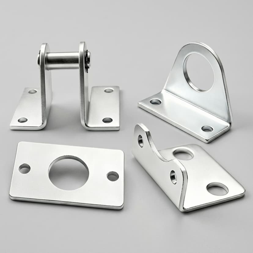
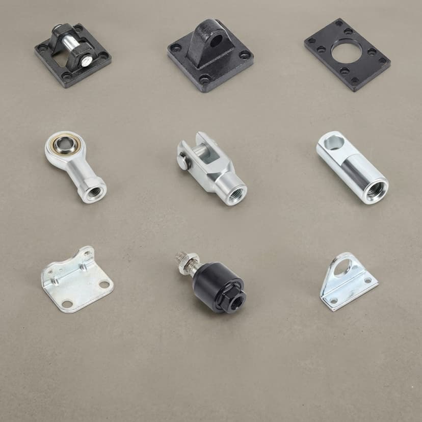
These images ground the page in real machined connector and clevis-style geometry. The exact routing still depends on the released drawing and inspection plan.
Use these pages when the broad actuator connector decision narrows into machining, production, inspection, or an adjacent component family.
Move from connector selection into machining route, tolerance, and RFQ evidence.
Understand tight tolerances, specific GD&T needs, and Class 3 thread fits for critical connectors.
Use when the question shifts from design triage to recurring production control.
Narrow into clevis geometry, pin loads, and cross-hole alignment.
Translate connector risks into FAI, CMM, gauge, and material evidence.
Compare connectors with housings, rods, shafts, glands, and brackets.
Send a drawing or CAD package when the connector load path is unclear.
Questions are grouped by the decisions buyers usually need to make before they can source or manufacture the connector.
An actuator connector is the end fitting or interface that transfers actuator force or torque into the moving load, bracket, linkage, valve stem, or driven member. Common forms include clevises, rod ends, eye ends, flanges, and custom couplings.
It can behave as either, but sourcing should follow the load path. If the clevis transfers actuator force through a pin and controls joint alignment, treat it as an actuator connector. If the main problem is bolting a stationary actuator body to a frame, treat it as a bracket.
Use a threaded rod end when axial load transfer, adjustable length, and compact assembly matter. Define thread standard, class, engagement length, relief, and anti-galling plan before release.
Choose a flanged connector when the interface must bolt to a face, adapter, valve, or driven plate and perpendicularity or sealing face control is more important than length adjustment.
Pin-hole true position, hole perpendicularity, thread axis runout or concentricity, flange face perpendicularity, bolt circle position, bearing fits, and datum faces usually need explicit controls.
ISO 2768-1 only covers general linear dimensions. ISO 2768-2 (geometrical tolerances) was withdrawn and replaced by ISO 22081:2021, which no longer contains fixed numerical tables. Load-bearing connector features must have explicit drawing-level geometric controls tied to function.
Class 2A/2B is standard and has an allowance for plating and easy assembly. Class 3A/3B has no allowance, offering high precision and zero backlash. Use Class 3 for aerospace or precision robotics, but warn the supplier—plating a Class 3 thread without pre-machining compensation will cause the thread to bind.
Single-setup or well-controlled indexed machining reduces stack-up between the actuator axis, thread axis, pin hole, and mating face. It is especially useful for clevises, flanges, and combined turned/milled rod ends.
A custom coupling is hard to quote when torque path, clamp or spline details, pin geometry, datum scheme, balance needs, or inspection method are missing.
High-load compact connectors often use alloy steel or precipitation-hardened stainless steel, but the right answer depends on corrosion exposure, load direction, thread form, finish, and required inspection evidence.
Stainless threads can gall because adhesive wear occurs under load when material pairing, surface finish, lubrication, hardness, or fit are not controlled. Avoid treating stainless as automatically safe for high-preload threads.
Aluminum can work for lightweight automation and robotics, but bearing surfaces and threads may need inserts, bushings, hardcoat anodize, or geometry changes if cyclic loads are high.
Include coating type, class, target thickness, masking rules, post-finish thread acceptance, corrosion requirement, and certificate needs.
Send a 2D drawing, 3D CAD model, material and condition, thread standard and class, pin or bearing fit, finish notes, batch quantity, inspection report needs, and target delivery date.
For critical connectors, request first article inspection, CMM data for datums and hole positions, thread go/no-go gauge records, pin or bore measurements, material certificates, and finish certificates.
No. The calculator is a DFM triage tool that identifies likely routing, risk, assumptions, and next steps. Final price and lead time require drawing review and supplier confirmation.
Define the load interface first. If the connector has no thread, pin, flange, clamp, or spline definition, send CAD and a drawing for engineering review before asking for a production quote.
Send the print, CAD model, material condition, thread callouts, and expected quantity so the machining route and inspection evidence can be confirmed.