
Actuator Connector Precision Machining
Ensure perfect alignment and load transfer with our precision machining services. Screen tight GD&T profiles, sub-thousandth positional targets, and Class 3 thread-fit risks for actuator clevises, rod ends, and flanges before committing a production quote.
Why Precision Dictates Performance
In high-performance linkages, small off-axis errors can turn intended axial force into side load on pins, bearings, and seals. Precision machining is valuable when it is tied to the functional datums and inspection evidence that prove those load-transfer relationships.
Tight tolerances only matter when tied to functional datums.
A sub-thousandth pin-hole or bearing-bore target is useful only when the drawing defines the actuator rod axis, pin axis, and load path as controlled datum relationships. Otherwise a precise single feature can still assemble out of line.
Single-setup routing reduces datum transfer risk.
Moving a connector between separate lathe, mill, and fixture operations can stack workholding variation into the thread axis, pin hole, or flange face. Mill-turn and 5-axis routes are preferred when the quoted tolerance depends on maintaining one functional setup.
Thread class and coating condition must be quoted together.
Class 3A/3B threads are often requested for tighter precision engagement, but plating, passivation, anti-galling choices, and gauge acceptance can change whether the finished part actually assembles.
Material condition dictates the tolerance strategy.
Heat treatment, cold work, and coating sequence can move thin tangs, threaded shanks, and press-fit bores after machining. Quote the alloy condition and post-process sequence before accepting tight tolerances.
Tolerance & Inspection Limits
How to keep precision claims quote-safe
The estimator gives a routing signal. The production quote becomes reliable only when the drawing, machining route, process sequence, and inspection evidence line up.
Define functional datums
Pin axis, rod axis, flange face, or bearing bore must be explicit before precision value can be assessed.
Select stable routing
Choose mill-turn, 5-axis, reaming, boring, or secondary grinding based on the features that share one setup.
Match process sequence
Heat treatment, plating, passivation, and hardcoat timing must be tied to the final measured condition.
Prove with inspection evidence
FAI, CMM, gauge logs, and surface texture readings close the gap between quote intent and shipped parts.
Precision Feature Matrix
Understand the machining strategies and required inputs for achieving tight tolerances on critical connector features.
| Feature | Routing Strategy | Quote Input Needed | Machining Boundary |
|---|---|---|---|
| Precision Clevis Tangs | 5-Axis Milling, Reaming | Pin hole diameter, tolerance, parallelism, true position | Ensure tang thickness is sufficient to resist deflection during machining. |
| Class 3 Threaded Shanks | CNC Turning, Thread Milling | Thread size, class, length, relief geometry | Galling risk in stainless steel; require anti-seize or specific hardness pairing. |
| Bearing Press Fits | Precision Boring, Reaming | Hole diameter, tolerance (e.g., H7), surface finish | Thin walls around the press fit can distort during insertion or machining. |
| Flange Perpendicularity | Face Milling or Turning | Perpendicularity tolerance to central axis, flatness | Clamping distortion during machining if the part is not properly supported. |
What the estimator should trigger next
Use these examples to interpret a routing signal without over-trusting it. Each case still depends on the released drawing and inspection plan.
Precision clevis for high-cycle linear actuator
- Inputs
- 17-4PH H1150, cross-hole true position, parallel clevis tangs, Class 3 external thread.
- Likely result
- High-complexity routing with datum-controlled milling/turning and CMM layout for pin-hole alignment.
- Next action
- Quote with final heat-treatment condition, pin diameter, thread gauge requirement, and FAI sample quantity.
Flanged connector for valve actuator
- Inputs
- 4140 alloy steel, perpendicular flange face, bolt-circle true position, zinc plating after machining.
- Likely result
- Stable production candidate if plating buildup is separated from before/after coating dimensions.
- Next action
- Define coating thickness allowance and ask for bolt-circle CMM data on first article and production samples.
Lightweight robotic rod-end adapter
- Inputs
- 7075-T6 aluminum, bearing press fit, hardcoat anodize, low-volume pilot build.
- Likely result
- Moderate-to-high risk because hardcoat and press-fit distortion can change the finished bore.
- Next action
- Confirm after-anodize bore target, plug gauge method, and whether a steel bushing is safer.
Undefined custom coupling
- Inputs
- No thread, no pin, no torque interface, and no datum reference frame available.
- Likely result
- Inconclusive. The estimator should ask for drawing definition rather than invent a routing or lead time.
- Next action
- Provide CAD, load direction, torque/force, mating part dimensions, and acceptance criteria before quoting.
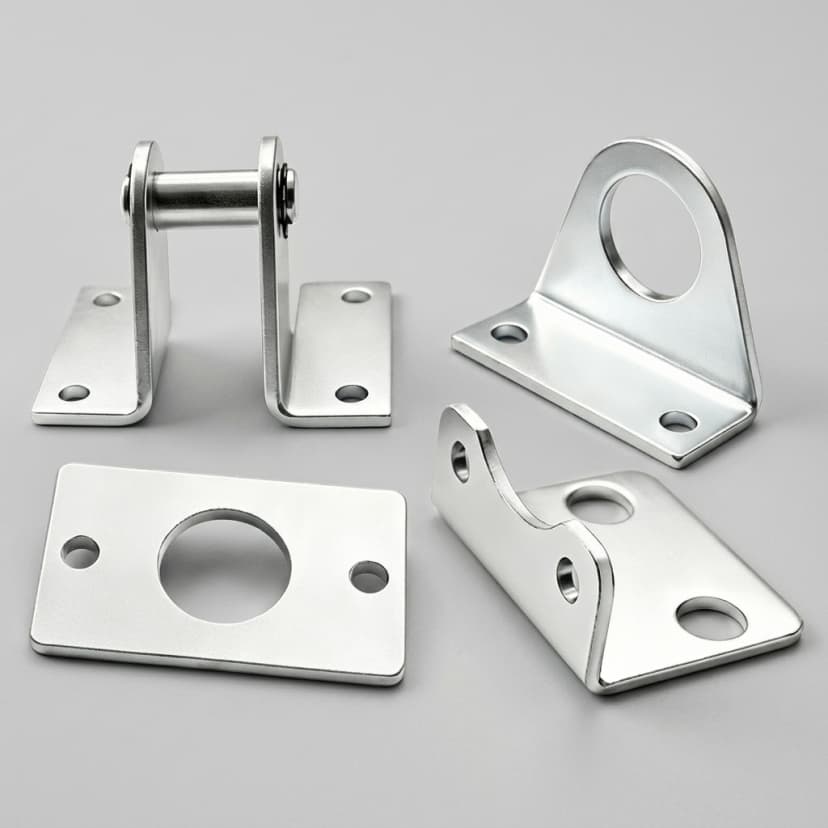
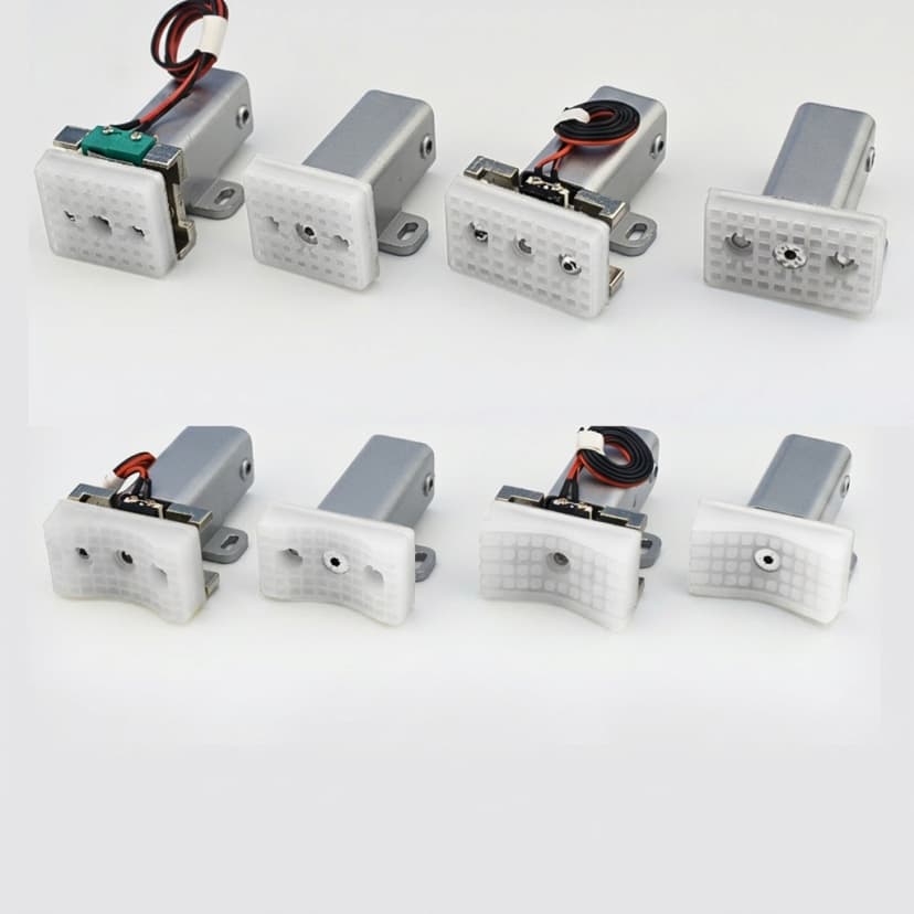
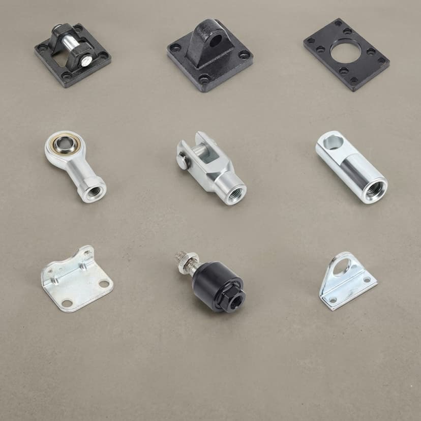
Precision Connector Visuals
Visualizing the complex geometries and high-quality surface finishes achieved through advanced multi-axis machining.
Standards & Source Validation
Public standards define the language, measurement framing, and acceptance tools used in precision connector quotes. They do not prove a supplier-specific capability by themselves; that proof comes from part-level FAI, CMM reports, gauge logs, and material records.
| Standard | Authority | Date Checked | Application | Limitation |
|---|---|---|---|---|
| GD&T datum and true-position language | ASME Y14.5 Dimensioning and Tolerancing | Checked July 23, 2026 | Defines the rules for establishing datums, true position, concentricity, and profile tolerances on precision drawings. | Must be properly applied by the design engineer to reflect the actual functional assembly. |
| Unified inch thread classes | ASME B1.1 Unified Inch Screw Threads | Checked July 23, 2026 | Guides the manufacturing and inspection of Class 3A/3B threads required for precision load transfer. | Only applies to standard UN series threads; custom threads require explicit tolerance callouts. |
| Thread gauge acceptance | ASME B1.2 Gages and Gaging for Unified Inch Screw Threads | Checked July 23, 2026 | Supports gauge-based acceptance planning for unified inch internal and external threads. | Does not replace buyer-specific sampling, torque, fatigue, or coating acceptance requirements. |
| Surface texture reporting | ASME B46.1 Surface Texture | Checked July 23, 2026 | Provides vocabulary and measurement framing for roughness, waviness, and lay on machined connector surfaces. | The correct Ra/Rz target still depends on the bearing, pin, seal, or coating system used in the assembly. |
| Aerospace Spherical Bearings | SAE AS81935 Standard | Checked July 23, 2026 | Frames bearing insert requirements where a spherical rod end is the selected connector architecture. | Primarily dictates bearing insert specifications, not the custom machined housing threads. |
Precision Inspection Protocols
| Inspection Category | Verification Method | Output Documentation | Failure Risk Mitigated |
|---|---|---|---|
| CMM Dimensional Inspection | Verify GD&T callouts like true position, concentricity, and parallelism using a Coordinate Measuring Machine. | First Article Inspection (FAI) report with CMM data. | Undetected misalignment causing premature actuator wear. |
| Thread Gauging | Inspect internal and external threads with calibrated Go/No-Go gauges. | Gauge inspection log confirming Class 3 fit. | Thread failure or excessive backlash under high loads. |
| Surface Roughness Verification | Measure critical mating surfaces and bearing holes using a profilometer. | Surface finish measurement report (Ra). | Poor finish leading to bearing wear or galling. |
Material Trade-offs for Precision
Rigid Clevis vs. Spherical Rod End
17-4PH Stainless Steel (H1150)
4140 Alloy Steel
7075-T6 Aluminum
Avoid These Design Risks
Tolerance Stack-Up
Signal: Drawings with chained linear dimensions instead of clear datum reference frames.
Impact: Parts may pass individual feature inspections but fail at assembly.
Mitigation: Apply GD&T correctly to relate critical features (like pin holes) to functional datums.
Post-Process Distortion
Signal: Specifying heat treatment after precision machining of thin-walled connectors.
Impact: Loss of concentricity, true position, and thread fit due to warping.
Mitigation: Machine from pre-hardened material or leave grinding allowance for post-heat-treat finishing.
Plating Build-Up
Signal: Tight tolerances (±0.0005") specified on parts requiring thick coatings like electroless nickel.
Impact: Holes become undersized and threads bind after plating.
Mitigation: Clearly specify dimensions as "after plating" or "before plating" and calculate allowances.
Precision Machining RFQ Checklist
Ensure you receive an accurate quote by providing these critical details when submitting an RFQ for precision actuator connectors.
Inquiry Email
Include drawings, material, finish, tolerances, quantity, and delivery location.
Frequently Asked Questions
What tolerances can you hold on precision actuator connectors?
For critical features like clevis cross-holes and bearing press fits, quote targets down to ±0.0005" (±0.0127 mm) can be reviewed when datum structure, material condition, fixture access, and CMM reporting are defined. General milled or turned profiles are commonly quoted less tightly unless the drawing requires otherwise.
How do you ensure concentricity between threaded shanks and connector bodies?
Concentricity is critical to avoid side-loading the actuator cylinder. For quote-critical features, we prefer multi-axis mill-turn or controlled secondary setups, then verify runout or position with a defined inspection method instead of assuming alignment from the route alone.
What surface finishes are standard for precision connectors?
Mating surfaces and pin holes are often quoted around 32 µin (0.8 µm) Ra when the mating part requires it. Dynamic sealing faces or high-cycle bearing interfaces may need tighter texture targets, secondary polishing, honing, or fine grinding.
Do you provide material traceability for precision machined connectors?
Yes. For high-reliability sectors, we provide full Material Test Reports (MTRs) tracing the alloy heat number, along with Certificate of Conformance (CoC) and dimensional inspection reports.
What materials are best for precision actuator connectors?
316L and 17-4PH stainless steels are preferred for corrosion resistance and high strength. 4140 alloy steel offers excellent fatigue life for heavy-duty uses. 7075-T6 aluminum is used for lightweight precision automation linkages.
How do you inspect the cross-hole true position?
We utilize Coordinate Measuring Machines (CMM) and calibrated pin gauges to verify the true position of cross-holes relative to the primary datum axis, ensuring perfect pin alignment during assembly.
What is required for a quote on a precision connector?
Provide a 2D engineering drawing with datums and GD&T, a 3D CAD model, material grade/condition specifications, batch quantity, and required inspection reports (e.g., FAI).
Can you handle low-volume prototype runs for precision connectors?
Yes, we specialize in high-mix, low-volume production. We can machine prototypes to validate fit and function before scaling to larger production batches.
Should tight dimensions be specified before or after plating?
Call out the measurement condition explicitly. Pin holes, bearing bores, and Class 3 threads usually need either after-plating dimensions or a defined pre-plate allowance, otherwise the coating can close the fit and create assembly failures.
When is precision actuator connector machining unnecessary?
If the connector is a low-load spacer, simple bracket, or non-critical cover with generous clearance, standard CNC machining and ISO 2768-style general tolerances may be enough. Reserve sub-thousandth tolerances for features tied to load transfer, bearing fit, thread engagement, or alignment.
Can the DFM estimator replace a drawing review?
No. The estimator screens routing risk from a limited input set. A released drawing, datum scheme, load case, material condition, and inspection plan are still required before committing tolerance, lead time, or production cost.
What shipment evidence should buyers request?
For critical connectors, request a material test report, certificate of conformance, first article inspection, CMM layout for GD&T features, thread gauge records, and surface finish readings for bearing or sealing interfaces.
Related Capabilities
Actuator connector CNC machining
Review general CNC routing, tooling, and cost drivers for standard actuator connectors.
Actuator connector factory
Compare factory qualification, production evidence, and release controls for connector programs.
Actuator component contract manufacturing
Learn how we manage the complete production lifecycle for complex actuator assemblies.
Actuator component inspection
Deep dive into CMM, surface finish, and GD&T verification processes.
Materials for actuator components
Compare the machinability and mechanical properties of precision alloys.