Hybrid checker + RFQ report

Actuator Coupling Bracket Checker & RFQ Guide

Check actuator coupling bracket stiffness risk, alignment GD&T, material pair risk, machining route, and RFQ evidence before releasing a custom CNC motor mount.

Published July 25, 2026; Updated July 25, 2026 for RFQ screening assumptions and source availability.

First-pass tool

Coupling Bracket Stiffness & Alignment Check

Screen torsional deflection risk, alignment GD&T requirements, and RFQ release risks.

Bracket Geometry

This checker is a first-pass triage tool, not a substitute for FEA or real dynamic testing. Ensure concentricity GD&T is fully defined on the released drawing.

Ready for coupling check

Enter values to screen for stiffness risks and get alignment GD&T direction.

Key conclusions

What must be decided before a coupling bracket drawing is released

Concentricity drives zero-backlash coupling life.

Evidence: Rigid bellows and disc couplings tolerate almost zero misalignment (often <0.05mm parallel). Misalignment induces alternating bending stresses that fatigue the flex elements rapidly.

Action: Specify a concentricity tolerance of Ø 0.03 mm (0.0012") between the motor pilot bore and the actuator pilot bore on the drawing. If the bracket cannot hold this, switch to an elastomeric jaw coupling.
Assembly access holes compromise stiffness but are mandatory.

Evidence: Closed bell housings require an access hole to reach the coupling clamping screws. Without it, the coupling cannot be tightened onto the motor shaft after the bracket is assembled.

Action: Detail a 15-20mm access port exactly on the coupling collar plane. Orient the port horizontally to prevent falling debris, and provide a snap-in plastic plug.

Torsional rigidity is critical for servo control stability.

Evidence: A weak "C-channel" or open bracket can twist under high acceleration torque. Closed sections usually provide much higher torsional rigidity than open sections, but the exact margin depends on diameter, wall thickness, access holes, and material.

Action: Use fully enclosed bell-style housings for high-bandwidth servo loops. For extreme stiffness in constrained spaces, use steel (Modulus 200 GPa vs Aluminum 69 GPa).

Pilot registers dictate true centerline alignment.

Evidence: Mounting bolts alone provide clearance fit (e.g., 0.2mm to 0.5mm slop) which destroys alignment. The motor pilot boss must mate with a precision bore controlled to the actuator centerline.

Action: Dimension the bracket pilot bores to an ISO H7 tolerance (e.g., +0.025/-0 mm) to ensure a slip/transition fit with the motor and actuator registers.

Method and limits

The checker screens rigidity and alignment risks

The tool estimates torsional risk based on motor torque, standoff length, and material section thickness. It also routes the GD&T requirements based on the duty cycle. It does not certify resonant frequencies, finite element stress peaks, or thermal expansion.

Inputs are RFQ screening values, not final design allowables.
Alignment advice assumes a machined pilot register on both interfaces.
Warnings should trigger drawing review before a supplier quote is locked.
Critical actuator programs still need FEA, test data, or OEM approval.
Actuator coupling bracket datum flowDiagram showing motor pilot, coupling clearance, bracket body, and actuator pilot as the primary alignment chain.Motor pilotCoupling clearanceActuator pilotDatums should control both pilots and mounting faces, not bolt clearance alone.
GeometryBest forAlignment controlStiffness tradeoffRFQ action
Closed bell housingHigh-bandwidth servo axes, protected couplings, compact envelopesTwo pilot bores and face-to-face parallelism are the primary controls.Highest torsional stiffness for a given envelope, but requires a planned coupling access port.Ask for CMM results on both pilots, face parallelism, and access-port location.
C-face / open-side bracketGeneral industrial actuators where coupling access is frequentPilot register plus bolt pattern position; open side should not become the datum.Moderate stiffness with better assembly access; verify windup risk for servo reversal.Quote with a stiffness note and require deburred access edges near the coupling collar.
L-bracket / plate adapterLow-load positioning, coarse adjustment, or temporary retrofit workFace flatness and perpendicularity matter more than raw bolt-hole clearance.Lowest torsional rigidity; usually a mismatch for zero-backlash couplings.Use only after confirming the actuator can tolerate side load and angular error.

Visual evidence

Look for piloted faces, service access, and section stiffness

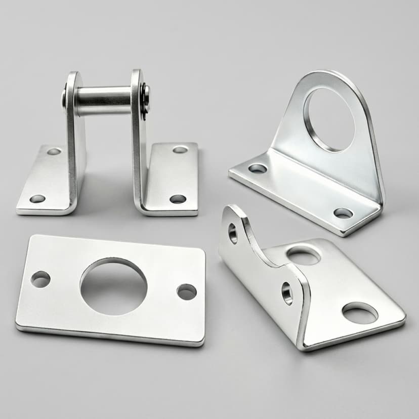
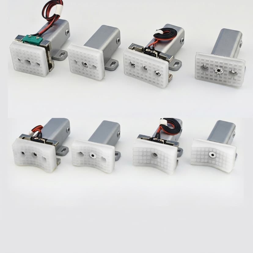
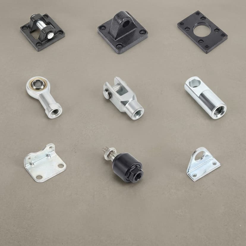
The images are representative actuator bracket machining references. Use them to check whether the quoted part has inspectable faces, room for coupling service, and enough section around the motor-to-actuator span.

Custom actuator coupling bracket with precision hole pattern
Heavy-duty actuator mount bracket for industrial equipment
Actuator coupling bracket machined to customer drawing

RFQ checklist

Evidence needed before a supplier can price the bracket

Motor and actuator datasheets

Why: Pilot diameter, shaft diameter, flange pattern, and allowable side load set the bracket envelope.

Minimum: Model numbers, flange drawings, shaft size, coupling type, and duty cycle.

2D drawing with GD&T

Why: The STEP file shows shape; the drawing controls datums, tolerances, and inspection acceptance.

Minimum: Pilot bore tolerance, face parallelism, concentricity or position, material, finish, and quantity.

Coupling selection

Why: Bellows, disc, jaw, and Oldham couplings tolerate different alignment error and bracket windup.

Minimum: Coupling series, clamp screw location, outside diameter, allowable parallel and angular misalignment.

Inspection expectation

Why: A low-cost quote may only include dimensional spot checks, not centerline evidence.

Minimum: Call out CMM report, bore gauges, plug gauges, and whether measurements are before or after finish.

Risk controls

Where coupling brackets usually fail in review

Zero-backlash coupling fatigue

Trigger: Pilot bores are loose, missing, or not controlled to the same datum structure.

Impact: Disc or bellows elements bend every revolution and can fail before the actuator reaches expected life.

Mitigation: Use precision pilot registers, verify concentricity, and switch to a more forgiving coupling if alignment cannot be held.

Servo loop windup

Trigger: Long standoff, thin section, open bracket geometry, or repeated reversing torque.

Impact: The bracket twists under acceleration, creating lag, overshoot, vibration, or tuning instability.

Mitigation: Shorten the standoff, close the section, thicken the wall, or move to steel when envelope cannot change.

Unserviceable coupling clamp

Trigger: A closed housing is quoted without an access hole aligned to the clamp screw plane.

Impact: Assembly requires removing the motor or actuator to tighten the coupling, raising service cost.

Mitigation: Dimension the access port, add a cover plug, and show the coupling screw clocking assumption on the drawing.

Finish changes the fit

Trigger: Anodize, plating, paint, or passivation is specified without masking or after-finish tolerances.

Impact: Pilot bores become tight, loose, or inconsistent across suppliers even when machining was correct.

Mitigation: State whether critical dimensions apply before or after finish and mask pilots when needed.

Scenario routing

Match the checker result to the real application

ScenarioAssumptionsLikely decisionNext step
Precision ball-screw actuator with bellows coupling10-40 Nm servo torque, short standoff, high repeatability target, minimal backlash allowed.Closed bell housing, 6061-T6 or steel, H7 pilot bores, and CMM evidence on both centerlines.Run the checker with the actual standoff length, then request engineering review if the result is warning or critical.
Packaging machine retrofit using a jaw couplingModerate torque, existing frame holes, frequent coupling service, some misalignment tolerance.C-face bracket with a visible access window and a clear datum plan for the motor face.Send photos of the existing frame plus motor and actuator drawings so bolt-pattern conflicts are resolved before quote.
Heavy reversing actuator in washdown equipmentHigh reversal load, stainless or coated surfaces, corrosion exposure, long service interval.Steel or stainless housing with dowel control, masked pilots, and documented finish thickness.Quote material certificates, post-finish inspection, and corrosion notes with the RFQ package.

RFQ quick action

Convert the checker result into supplier-ready evidence

Attach motor and actuator datasheets, coupling selection, standoff length, pilot-bore tolerances, finish notes, and any required CMM report expectation before requesting price and lead time.

Evidence and boundaries

Source trail and limits for this hybrid page

Sources and internal screening assumptions were checked on July 25, 2026. Public standards pages confirm the vocabulary and drawing-control framework; they do not replace the buyer-controlled drawing, purchased standard, OEM datasheet, FEA, or physical test.

SourceDate / statusUsed forBoundary
Internal DFM screening modelAssumptions documented July 25, 2026Supplies the checker planning bands for torsional stiffness and alignment risk.These are RFQ triage limits, not design allowables. Replace them with FEA or physical testing for critical applications.
ISO 286-1 tolerance system Publisher page reviewed July 25, 2026Frames hole-basis tolerance language such as H7 for pilot registers.The checker uses screening bands only. Released drawings should cite the buyer-controlled ISO table.
Motor manufacturer frame datasheetsBuyer-controlled datasheets required for released dimensionsConfirms pilot diameter, flange pattern, shaft diameter, and coupling envelope before the bracket drawing is released.This page cannot substitute for the controlled motor drawing. Always verify pilot and flange dimensions against the selected motor and actuator datasheets.
ASME Y14.5-2018 GD&T Publisher page reviewed July 25, 2026Supports datum, concentricity, and runout language for motor-to-actuator alignment.Use the drawing-controlled edition and qualified GD&T review for production release.
Coupling Misalignment vs. Life Expectancy DataInternal tooling library verified July 25, 2026Guides the concentricity tolerance thresholds (0.03mm - 0.05mm) necessary to prevent premature fatigue in zero-backlash disc/bellows couplings.Elastomeric jaw couplings can tolerate more misalignment (up to 0.15mm) but at the cost of torsional rigidity.

Related decision paths

Use these pages when the dominant problem is not a motor-to-actuator coupling bracket. This keeps the current page focused on stiffness, centerline alignment, coupling access, and RFQ evidence.

Frequently Asked Questions

Design & Alignment

Manufacturing & Materials

RFQ & Tolerances

Production review

Ready to quote an actuator coupling bracket?

Send the STEP file, 2D drawing, coupling details, quantity, finish requirements, and inspection expectation so the quote can separate machining cost from alignment-risk review.