
Separate enclosure protection from pressure capacity
Agree the assembly test requirement first. An IP label is not a pressure rating or a universal cover tolerance.
IEC 60529 scopeDesign guide + routing checker
An actuator cover closes or shields a motor, gearbox or end compartment. This guide helps buyers and designers plan custom rigid metal covers, including linear actuator and motor covers. Enter dimensions to screen machining priorities; results do not certify strength, sealing or replacement compatibility.
Published · Reviewed by Actuator Machining, a site operated by Magatom Dynamics Co., Ltd..
Agree the assembly test requirement first. An IP label is not a pressure rating or a universal cover tolerance.
IEC 60529 scopeEx d construction and testing require a separate review against the applicable standard and certified design. The routing score cannot approve a flameproof joint or a replacement cover.
IEC 60079-1 scopeUse the selected static gland chart and preserve its roughness metric and units. Parker §4.1 uses RMS; relabeling those values as Ra can change the drawing requirement.
Parker handbookAgree buildup and masking before machining. Type III anodizing and deposited nickel need different allowances; accept the final bore, sealing face, and thread fit after finishing.
Finishing comparison and sourcesDo not treat 316L as universally seawater-safe. Ask for the medium, temperature, cleaning cycle, and crevice conditions.
Manufacturer guidance| Cover function | What to establish | Next action |
|---|---|---|
| Motor / gearbox enclosure | Mounting interface, cable entries, environmental seal, service access | Use this checker, then review the assembly drawing. |
| Explosion-proof (Ex d) cover | Certified joint geometry, gap, length, finish, and applicable standard edition | Use a qualified hazardous-area design review. This checker cannot approve an Ex d cover or an OEM substitution. |
| Pressure-bearing end cover | Pressure, loads, fasteners, seal extrusion gaps, validation requirements | Commission a pressure and structural review regardless of this score. |
| External guard or weather shield | Clearances, access, drainage, attachment, protective function | Review the guard design; the machining checker may not be relevant. |
| OEM replacement cover | Model, serial number, original drawing and seal compatibility | Confirm the OEM part and revision before assuming interchangeability. |
For external shields see actuator cover machine guards. For supplier process details see actuator cover CNC machining.
This is an editorial planning heuristic, reviewed 2026-09-22, not a validated engineering model. Ratio = OD or maximum span ÷ overall thickness, both in mm. It does not model stiffness. The cutoffs below are review prompts, not standards or supplier capacity limits.
| Input / condition | Points | Manual-review trigger |
|---|---|---|
| OD/thickness > 10 | +1 | Yes when combined with complex ports. |
| Thickness < 8 mm | +1 | Yes with complex ports or high-pressure / seal-groove features. |
| OD/span > 300 mm | +1 | Always: review machine envelope and support. |
| Stainless or alloy steel | +1 | No automatic trigger; review grade and condition. |
| Complex ports / threads | +1 | As above for thin or high-ratio geometry. |
| High pressure / seal grooves | +2 | Thin geometry triggers process review. All pressure designs need separate qualification. |
Only the listed conditions contribute points. Low does not mean approved, and High does not mean impossible. Square, asymmetric, pocketed, or ribbed parts need drawing review because a single ratio misses their local geometry.
Have a drawing ready? Use the drawing-review checklist to record final fits, seal details and inspection needs.
| Material option | Required review | Cost / compatibility uncertainty |
|---|---|---|
| Aluminum (6061 / 7075) | Specify alloy, temper, finish, and mating materials. | Coating allowance and masking can change routing. See AAC source. |
| Mild / carbon steel | Specify grade, protection system, and inspection condition. | Finishing and protection requirements are not priced here. |
| Alloy steel (4140) | Specify heat treatment, hardness, and final machining sequence. | The checker adds one planning point; actual machinability depends on condition. |
| Stainless steel | Specify grade and environment; do not infer seawater suitability from 316L alone. | Corrosion and cycle-time performance require application review. See Outokumpu source. |
| Brass / bronze | Specify the exact alloy, loading, and fluid compatibility. | The combined menu category is not a material equivalence claim. |
| POM / titanium / other | Outside this checker; use a material-specific drawing review. | No score or automatic substitution is supported. |
Select the applicable static face or radial gland from the Parker handbook. Section 4.1 gives general guidance of 32 µin RMS for static sealing surfaces and 16 µin RMS for face-type gas seals. These are RMS values, not Ra specifications. Select the applicable chart and record seal size, compound, medium, temperature, gland dimensions, and squeeze requirements for the actual joint.
Flatness must follow the joint analysis and test plan. This page supplies no universal groove tolerance or flatness value for IP67/IP68. Verify the complete enclosure, including fasteners, cable entries, and the mating housing.
Have the reviewer consider machining lay across the sealing path and inspection after finishing. A surface-finish number alone cannot predict leakage. For Ex d flamepaths, use a separate review of the certified design and applicable IEC 60079-1 requirements; neither an IP label nor this checker establishes flameproof compliance.
The AAC Type III guide describes approximately half penetration and half surface buildup for hard anodizing. Example only: a specified 50 µm coating implies about 25 µm buildup per surface; a bore coated on opposing sides could close by about 50 µm in diameter. This is a planning approximation, not a coating specification.
Electroless nickel adds a deposited layer. The Nickel Institute guide explains that uniformity depends on consistent solution conditions. This does not guarantee a fixed tolerance for every geometry. Assuming 25 µm is deposited on each opposing bore surface, the geometric diameter reduction is 2 × 25 = 50 µm; pretreatment removal and local coating variation still need review.
| Finish | Planning example | Confirm before release |
|---|---|---|
| Type III anodizing | 50 µm total coating, assuming half buildup: about 25 µm per surface; bore diameter decreases about 50 µm. | Alloy, pretreatment, masking, coating thickness and final fit. The buildup fraction is approximate. |
| Electroless nickel | 25 µm deposited on each bore surface: calculated diameter decrease of 50 µm before other dimensional changes. | Solution access, local thickness variation, pretreatment removal and final fit. No universal ±2.5 µm tolerance is claimed. |
| Either process: insufficient data | Final allowance is unknown until the coating specification and local acceptance limits are agreed. | Request a finishing review or discuss masking critical fits before releasing the machining drawing. |
Always agree on coating thickness, process tolerance, masked areas, and post-finish acceptance with the finisher. Thread pitch stays as specified; fit compensation requires the thread geometry and finish process.
| Inputs | Calculation → result | Decision |
|---|---|---|
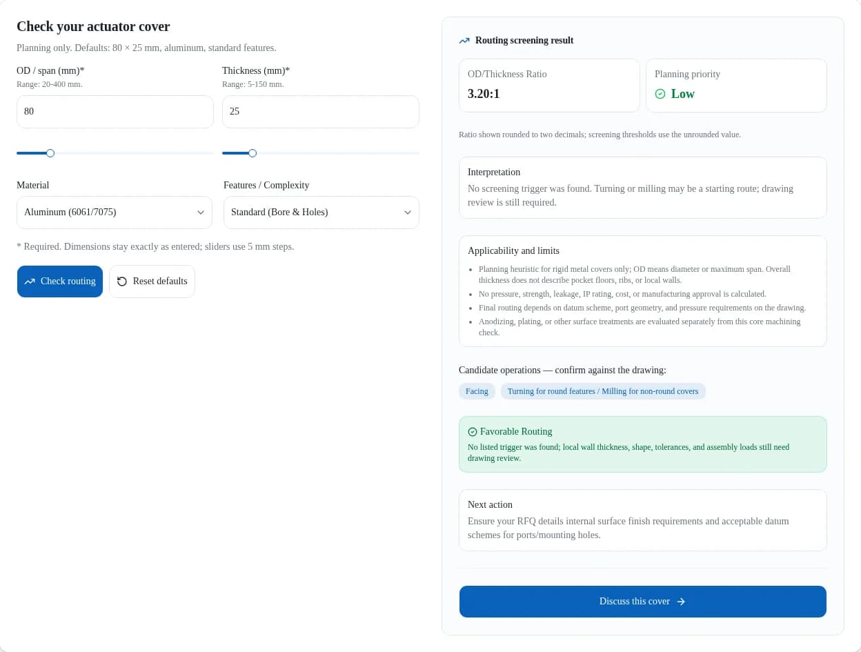
| 80 × 25 mm, aluminum, standard | 80/25 = 3.2; 0 points → Low | Prepare the mating drawing, tolerances, and finish requirements. |
| 80 × 25 mm, aluminum, complex ports | 3.2 ratio; ports +1 → Medium | Review port access, deburring, and setup count. |
| 240 × 6 mm, stainless, complex ports | 40.0 ratio; +1 ratio, +1 thin, +1 material, +1 ports = 4 → High + manual review | Review remaining walls and support before committing to a process. |
| Risk | Unknown in this tool | Minimum next step / alternative |
|---|---|---|
| Misuse: treating Low as approval | Pressure capacity, leakage, fatigue, seal performance | Separate process planning from structural and assembled-enclosure validation. |
| Cost: excess setups or finish rework | Quantity, port access, masking, inspection time, supplier capacity | Request a drawing-based quote with finish and inspection scope; discuss accessible ports or simpler features. |
| Scenario mismatch: thin pocket floor | Minimum local walls, ribs, unsupported span, clamps | Send a section view; consider more support or revised geometry with the designer. |
| Input outside 20–400 / 5–150 mm | No supported automatic screen | Keep the actual dimensions and use manual review; do not scale the part to force a score. |
Reviewed . Manufacturer and standards references support the report’s design questions. None validates the checker’s scoring thresholds, predicts manufacturing yield, or supplies a price.
Edition 2.2 (2013), consolidated with listed corrigenda. Public scope confirms enclosure classification; the full test requirements require access to the standard. It is not a machining drawing.
Edition 7.0 (2014), including the listed 2018 corrigendum and 2020 interpretation sheet. The public scope covers construction and testing of flameproof electrical enclosures. Detailed joint requirements need the applicable standard and certified design; this page supplies no flamepath acceptance dimensions.
Section 4, §4.1: static sealing guidance uses microinch RMS, including 32 µin RMS for static sealing surfaces and 16 µin RMS for face-type gas seals. These are general guidelines, not universal Ra limits; choose the applicable gland chart and review machining lay.
Type III section: coating thickness includes penetration and buildup. Its 50/50 guidance is a planning approximation; confirm alloy, process, masking, and final dimensions with the finisher.
Technical guide, deposit uniformity discussion. Uniform deposition depends on consistent solution conditions, including temperature, pH, agitation, and composition. It does not establish a universal finished-part tolerance. Obtain the full guide and agree local coating acceptance with the finisher.
2025 manufacturer guidance: exposure severity and chloride deposits matter. Atmospheric material selection does not establish suitability for permanent seawater immersion.
A cover closes or shields part of an actuator, such as a motor, gearbox, switch compartment, or cylinder end. Some covers carry pressure or load; others only protect against contact or contamination. Identify that function before selecting a design.
No. For an OEM replacement, record the manufacturer, model, serial number, drawing revision, and seal kit. An outside diameter alone cannot establish interchangeability.
No. The tool does not use pressure, bolt preload, unsupported span, fatigue, or seal properties. Every pressure-bearing design needs a separate engineering assessment and an agreed validation plan.
Do not derive a universal machining tolerance from an IP label. IEC 60529 classifies enclosure protection. Select cover tolerances from the actual joint design and validate the assembled enclosure to the applicable requirements.
Overall thickness can hide a thin pocket floor or sidewall. Send a sectioned drawing with minimum remaining walls, ribs, and clamping surfaces for review, regardless of the score.
Decimals are accepted inside OD/span 20–400 mm and thickness 5–150 mm. Empty and out-of-range inputs stop the check and remain unchanged. Use manual review for geometry outside this screening range.
Those materials are outside this checker’s material options. Do not substitute aluminum to obtain a result. Request a material-specific review with the grade, temperature, loading, and exposure conditions.
Specify the required thread fit after finishing and agree compensation or masking with the finisher. Coating affects fit and pitch diameter; changing the nominal thread pitch is not a compensation method.
Include the result, a dimensioned drawing, minimum local walls, material and condition, ports and threads, seal details, final finish dimensions, quantity, and test requirements. Ask the supplier to confirm machining, finishing, and inspection scope in the quote.
Contact the team or review the mating actuator body and connector interfaces.
Inquiry Email
Include drawings, material, finish, tolerances, quantity, and delivery location.