
CNC Machining Smart Actuator Housings: DFM Strategies for IoT Sensor Integration
CNC machining smart actuator housings guide for IoT sensor pockets, EMI shielding, IP sealing, tolerances, inspection, and RFQ planning. Request DFM input.
The industrial landscape of 2026 is driven by data. CNC machining smart actuator housings with embedded IoT sensors requires more than a motor enclosure; it requires a sealed, shielded, inspection-ready chassis. As manufacturing plants transition fully into Industry 4.0, the humble actuator—historically a passive mechanical device—has been transformed into an intelligent, data-gathering node. Today’s "smart actuators" are embedded with an array of IoT sensors, including strain gauges, accelerometers, thermal probes, and absolute encoders. This evolution shifts the burden of complexity directly onto the mechanical design and the CNC machining process.
For buyers, procurement teams, and mechanical engineers, sourcing the housing for a smart actuator is no longer just about containing a motor and a geartrain. It is about manufacturing a high-precision, environmentally sealed, electromagnetically shielded enclosure that seamlessly interfaces with delicate microelectronics. This guide explores the critical Design for Manufacturability (DFM) strategies, CNC machining tolerances, and procurement considerations for smart actuator housings. If you are scoping a new actuator program, compare these requirements against Actuator Machining's CNC machining capabilities and actuator component portfolio before freezing the RFQ.
Scope note: This article was published and last reviewed on July 18, 2026 for global industrial OEM, automation, aerospace, food-processing, marine, and heavy-equipment sourcing teams. The tolerance and finish values below are planning ranges for machined housings; always validate them against the drawing stack-up, local compliance requirements, operating duty cycle, media exposure, and final sensor vendor specifications.

1. The Paradigm Shift: From Mechanical Enclosure to Smart Chassis
Historically, an actuator housing served three primary functions: supporting the mechanical load, protecting internal components from the environment, and dissipating heat. In the era of smart manufacturing, the housing must now accommodate complex electronic architectures.
Embedding sensors directly into the mechanical chassis provides the most accurate real-time data for predictive maintenance. However, this integration introduces severe machining challenges:
- Complex Geometries: Housings now require intricate internal pockets, micro-channels for wire routing, and precision-tapped holes for PCB standoffs.
- Vibration Isolation: Sensor cavities must be machined to exact dimensions. A loose fit allows vibration, leading to false sensor readings or premature electronic failure.
- Thermal Management: The housing must simultaneously act as a heat sink for the motor and a thermal shield for the sensitive microcontrollers.
Failure to account for these factors during the CNC machining process results in high scrap rates, compromised environmental sealing, and ultimately, field failures of the actuator.
2. CNC Machining Strategies for Sensor Integration
When an actuator housing is designed to hold IoT components, the CNC machining approach must adapt. The traditional 3-axis milling process is often insufficient due to the multiple angles required for connector ports and sensor cavities.
5-Axis Simultaneous Machining
To achieve the true positional accuracy required for intersecting wire channels and sensor pockets, 5-axis CNC machining is almost mandatory. By machining the bearing bores, motor mounts, and electronic cavities in a single setup, the machinist eliminates the stack-up errors associated with manually flipping the part. This is critical when a wiring channel must perfectly align with a secondary connector port on a different face of the housing.
Micro-Machining and Tooling
Creating pockets for micro-sensors often requires endmills smaller than 1mm in diameter. Machining these features deep inside an aluminum or stainless steel housing requires high-speed spindles (often exceeding 30,000 RPM) and optimized toolpaths to prevent tool breakage and ensure a pristine surface finish.
Internal Corner Radii
A common DFM mistake is designing perfectly square pockets for PCBs. CNC endmills are cylindrical and naturally leave a radius in internal corners. To minimize machining costs and cycle times, engineers should specify the largest acceptable internal corner radius (e.g., R3.0mm or greater). If a perfectly square PCB must fit into the pocket, engineers should design "dog-bone" or "Mickey Mouse" corner reliefs into the CAD model.
3. Sensor Cavity Machining Tolerances & DFM
The precision required for the electronic cavities in a smart actuator housing often exceeds the requirements for the mechanical geartrain. The table below outlines the recommended tolerances and DFM guidelines for various integrated sensor features.
| Feature Type | Typical CNC Tolerance | Surface Finish (Ra) | DFM & Machining Strategy | Common Application |
|---|---|---|---|---|
| PCB Mounting Pockets | +0.05mm / -0.00mm | 1.6 μm (63 μin) | Use largest possible corner radii. Include dog-bone corner reliefs to avoid secondary EDM operations. | Main microcontroller, IoT connectivity module. |
| Vibration Sensor Bores | ±0.01mm (H7 Fit) | 0.8 μm (32 μin) | Bore must be perfectly cylindrical. Often requires a final reaming pass. Bottom surface must be perfectly flat for acoustic coupling. | Predictive maintenance, bearing wear detection. |
| Thermal Probe Channels | ±0.05mm | 3.2 μm (125 μin) | Drill using high-pressure through-tool coolant to maintain straightness in deep holes. Position close to motor/bearings. | Overheat detection, duty-cycle monitoring. |
| Wiring Harness Micro-Channels | ±0.10mm | 3.2 μm (125 μin) | Deburr heavily. Any internal burr or sharp edge will strip wire insulation over time, causing short circuits. | Routing power and data from sensors to the main PCB. |
| O-Ring Glands (IP67/IP69K) | ±0.02mm | 0.4 μm (16 μin) | Requires specialized grooving tools. The bottom and sides of the gland must be free of tool marks to ensure a hermetic seal. | Sealing the electronic cavities from external fluids. |
| Connector Ports (M12/M8) | ±0.05mm | 1.6 μm (63 μin) | Thread milling is preferred over rigid tapping for superior thread quality and alignment. | External data and power interface. |
4. EMI/RFI Shielding and Material Considerations
Electromechanical actuators generate significant electromagnetic interference (EMI) due to the switching frequencies of the internal motor drives. When sensitive IoT sensors are placed within millimeters of these motors, shielding becomes a critical design parameter.
Machining Aluminum vs. Stainless Steel
Aluminum (6061-T6 or 7075-T6) is the most common material for smart actuator housings due to its excellent machinability, light weight, and natural EMI shielding properties. Aluminum acts as a highly effective Faraday cage, protecting the internal electronics from both internal and external interference. However, to maintain shielding continuity across multi-part housings, the mating surfaces must be machined to extremely tight flatness tolerances (often <0.02mm) to ensure full metal-to-metal contact. For alloy trade-offs, corrosion exposure, and finish selection, align early with the machining materials guide.
Stainless Steel (316L) is used in aggressive environments (food processing, marine, chemical). While it offers superior corrosion resistance, it is more difficult to machine, increasing cycle times and tooling costs by up to 300% compared to aluminum. Its EMI shielding properties are also different, sometimes requiring thicker walls to achieve the same attenuation.
Surface Treatments and Shielding Continuity
A critical factor often overlooked by procurement teams is the impact of surface treatments. Anodizing aluminum creates a durable, corrosion-resistant surface, but the aluminum oxide layer is a strict electrical insulator. If an actuator housing is fully anodized, the EMI shielding continuity between the housing sections is broken. To solve this, the CNC machining process must include secondary operations to mask off the mating flanges before anodizing, or a post-machining operation (like laser ablation or light face milling) must be used to remove the anodized layer from the critical contact areas. Alternatively, conductive conversion coatings (like Alodine/Chem Film) can be applied to the mating surfaces.
5. Sealing Strategies for Harsh Environments (IP67 / IP69K)
Smart actuators are frequently deployed in harsh environments—from automated agricultural equipment to pharmaceutical washdown lines. The electronic cavities must be hermetically sealed to prevent moisture ingress, which would instantly destroy the IoT sensors.
Achieving IP67 (immersion up to 1 meter) or IP69K (high-pressure, high-temperature washdown) ratings places extreme demands on the CNC machining of the housing's sealing interfaces.
- O-Ring Gland Surface Finish: The surface finish of the O-ring groove is paramount. A finish of Ra 0.4 μm (16 μin) or better is typically required. Any chatter marks, tool step-overs, or microscopic scratches left by the CNC endmill will act as a capillary path for water under pressure.
- Flange Flatness: The mating flanges must be incredibly flat to ensure uniform compression of the gasket or O-ring. If the CNC machine lacks rigidity, or if the clamping forces warp the part during machining, the resulting housing will inevitably leak.
- Fastener Spacing and Rigidity: The housing must be thick enough to allow for sufficiently close fastener spacing. If the screws are too far apart, the housing will bow between the fasteners under pressure, compromising the seal.
6. Procurement, Inspection, and Inquiry Checklist for Smart Housings
For procurement professionals, sourcing the machining for a smart actuator housing is significantly riskier than sourcing a standard mechanical bracket. The supplier must understand both precision mechanical engineering and the unique requirements of electronic enclosures.
Use this checklist when vetting CNC machining partners and preparing your RFQ (Request for Quote) inquiry:
Supplier Capability Validation:
- 5-Axis Capabilities: Does the supplier have true 5-axis simultaneous machining capabilities to handle complex, multi-angled sensor pockets and connector ports in a single setup?
- Deburring Expertise: Do they have automated or highly controlled manual deburring processes? (A single hidden burr in a wire channel can slice a sensor wire and destroy the actuator).
- CMM Inspection: Can they provide comprehensive CMM (Coordinate Measuring Machine) reports verifying the true position and GD&T of the electronic cavities relative to the mechanical bearing bores?
- Quality Documentation: Confirm whether the supplier can package first-article inspection, in-process checks, and CMM outputs in a format compatible with your quality and traceability requirements.
Specification and Inquiry Fields (RFQ Checklist):
- Material Grade & Certification: Specify the exact grade (e.g., Al 6061-T6, SS 316L) and request material test reports (MTRs).
- EMI Shielding Requirements: Explicitly state if post-machining masking or conductive conversion coatings are required for continuous Faraday cage protection.
- IP Rating (Sealing): Specify IP67 or IP69K. Define O-ring gland surface finish requirements (e.g., Ra < 0.4 μm) and geometric tolerances.
- Vibration Environment: Indicate the operational frequency and amplitude. Request H7 or tighter fits for sensor pockets to avoid resonance.
Acceptance and Delivery:
- Cleanliness Standards: Are they equipped to ultrasonically clean and package the housings to prevent microscopic metal shavings from contaminating the electronic assemblies?
7. Application Boundaries, Failure Risks, and Buyer Decision Points
When integrating smart housings, recognizing the mechanical and operational boundaries is crucial to prevent premature failure.
Applicability Boundaries: Smart actuator housings are ideal for critical process controls (e.g., chemical dosing, aerospace control surfaces) where predictive maintenance justifies the extra CNC complexity. They are typically overkill for basic ON/OFF material handling conveyors, where standard cast or extruded housings suffice.
Failure Risks and Mitigation:
- Resonant Vibration Amplification: If sensor pockets are machined with excessive clearance (loose tolerances), the sensor will rattle. This noise corrupts accelerometer data and leads to premature wire fatigue. Mitigation: Demand H7 fit tolerances and specify potting compounds for final assembly.
- Galvanic Corrosion: Mixing an aluminum housing with stainless steel fasteners and embedded copper/gold PCB traces in a humid environment invites galvanic corrosion. Mitigation: Ensure proper anodizing or conformal coating, avoiding direct dissimilar metal contact near the electronic bays.
Buyer Decision Points: When issuing a PO (Purchase Order), buyers must decide between a single-piece monolithic housing versus a multi-piece bolted assembly.
- Monolithic (Single-piece): Higher initial machining cost (requires advanced 5-axis work), but guarantees superior IP rating and eliminates EMI leakage through seams.
- Multi-piece: Lower machining costs (can use 3-axis mills), but requires high-precision O-ring grooving, flange flatness checks, and conductive gaskets to prevent EMI/environmental leaks.
8. Frequently Asked Questions (FAQ)
Q1: What is the typical machining tolerance required for an embedded PCB pocket? Unlike standard mechanical clearances, PCB pockets often require +0.05mm / -0.00mm. A pocket that is too small will crack the board upon insertion, while one that is too loose will subject the IoT sensors to resonant vibration, drastically reducing their lifespan.
Q2: How do we prevent EMI interference from the motor affecting the smart sensors? Beyond electrical filtering, the CNC machined housing itself must act as a Faraday cage. This involves machining tight-tolerance interlocking flanges with conductive gaskets, and avoiding large unshielded wiring channels. When machining plastic housings, conductive coatings must be applied post-machining.
Q3: Does adding sensor cavities weaken the actuator housing's structural integrity? It can, especially in high-pressure hydraulic or heavy-duty electromechanical applications. FEA (Finite Element Analysis) is required. CNC programmers must use strategies like maintaining a minimum wall thickness of 3mm in aluminum and avoiding sharp internal corners (using corner radii >2mm) to prevent stress concentrations.
Q4: Why is 5-axis CNC machining recommended for smart housings? Smart housings feature multiple intersecting features—such as bearing bores on one axis, and sensor pockets, wiring channels, and connector ports on oblique angles. 5-axis machining allows these to be cut in a single setup, eliminating stack-up tolerance errors that occur when parts are manually repositioned.
Q5: What are the cost implications of upgrading from a standard housing to a smart IoT-enabled housing? Integrating sensor pockets, micro-channels, and tighter EMI flange tolerances typically increases the CNC machining cycle time by 40% to 80%. Buyers should expect higher NRE (Non-Recurring Engineering) costs for 5-axis programming and specialized micro-endmills.
9. The Future of Smart Actuator Manufacturing
As we move further into the decade, the convergence of mechanical actuation and digital intelligence will only accelerate. We are beginning to see the integration of entirely new sensor modalities, such as acoustic emission sensors for detecting microscopic gear fractures before they propagate.
This evolution demands a closer partnership between design engineers, procurement teams, and CNC machining suppliers. By understanding the intricate DFM requirements—from corner radii and tolerance stacking to EMI shielding and IP69K sealing—organizations can successfully navigate the complexities of manufacturing the next generation of intelligent motion control systems.
If your engineering team is developing a new line of smart actuators, collaborating with a machining partner early in the design phase is critical. Optimizing your housing for manufacturability will significantly reduce production costs, minimize lead times, and ensure the long-term reliability of your IoT integration. To review a drawing package or discuss manufacturability risks before release, contact Actuator Machining with the CAD model, target material, annual volume, IP rating, and inspection requirements.
Sources & References
- Design for Manufacturability (DFM) Principles, Wikipedia. https://en.wikipedia.org/wiki/Design_for_manufacturability
- CNC Machining: Optimizing Internal Corner Radii, Xometry. https://www.xometry.com/resources/machining/cnc-machining-optimizing-internal-corner-radii/
- How Corner Radius Affects CNC Machining, Protocase. https://www.protocase.com/blog/2020/03/06/how-corner-radius-affects-cnc-machining/
- Enclosure Level EMI Shielding, Laird. https://www.laird.com/products/enclosure-level-emi-shielding
Author

More Posts
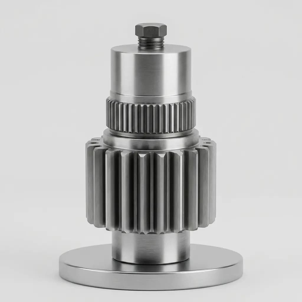
Dimensional Inspection for OEM Actuator Parts: CMM, Profilometers, and First Article Approval
A buyer's guide to First Article Inspection (FAI), CMM measurements, surface roughness (Ra/Rz), and material traceability for outsourced actuator components.
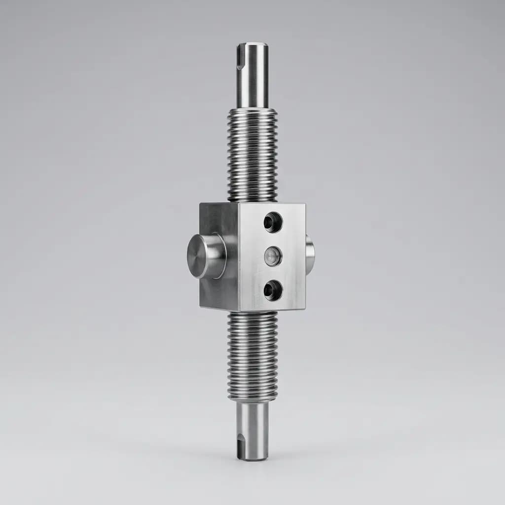
Actuator Machining EU CBAM 2026 Downstream Risk
Actuator machining buyers: map EU CBAM downstream risk, 2028 exposure, TARIC codes, PCF data, and RFQ clauses before quoting.
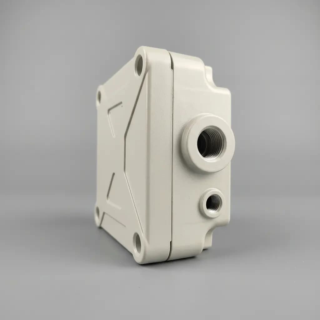
Procuring Machined Actuator Parts in 2026: Why Data Sovereignty Matters
Discover why EU Data Act compliance, MTConnect logs, and process reliability have become more critical than unit cost when sourcing CNC machined actuator components.