Evaluate actuator cap manufacturability. Check if your cap design is a simple turning job or requires complex mill-turn routing before you send the RFQ.
Tool output explains aspect ratio risks, routing operations, and next actions.
Report layer separates material facts, process capability, and quote-dependent assumptions.
Published July 11, 2026; Updated July 11, 2026; sources are linked below.
Use these conclusions to assess your cap design's complexity and ensure your drawing includes necessary specifications.
Published July 11, 2026 / Updated July 11, 2026
Mill-turn capability reduces setup variance.
For caps with threaded side ports or asymmetric features, using a single setup on a mill-turn machine eliminates rechucking errors and improves bore-to-port positional accuracy.
Evidence basis: Process engineering data & geometric dimensioning (GD&T) principles
Seal groove finish is a critical acceptance point.
Seal-groove dimensions and surface texture should be specified beside the seal supplier data. Public ISO pages define housing frameworks; final Ra and tolerance values remain drawing- and seal-dependent.
Evidence basis: ISO 3601-2:2025 and ISO 5597:2018 scope statements + RFQ drawing requirements
Material choice is not the pressure rating.
6061-T6 aluminum is fast to machine and corrosion resistant, while 1045 steel provides higher strength but slower machining. Actual pressure capacity depends on wall section, port geometry, fatigue margin, seal design, and safety factors.
Evidence basis: Public 6061 and 1045 material datasheets + pressure-design dependency disclosure
Thin caps require specialized workholding.
Caps with a high OD-to-thickness ratio can warp or distort when chucked. Soft jaws or pie jaws are necessary to maintain flatness and cylindricity.
These are process planning inputs, not universal guarantees. Final acceptance depends on the drawing tolerances, thread specifications, seal supplier data, coating stack, and inspection methods.
Mill-Turn Integration
Caps with fluid ports, mounting flanges, or intersecting holes are best machined on multi-axis turning centers with live tooling. This eliminates secondary setups and guarantees tight concentricity and true position between turned features and milled features.
Seal Groove Precision
Conforming to ISO 3601-2 and ISO 5597, static and dynamic seal housings require controlled diameter, depth, extrusion gap, and surface texture callouts. The exact groove tolerance and Ra value must come from the drawing and seal supplier, not from a generic page assumption.
Burr Control in Intersecting Ports
Cross-drilled ports create internal burrs that are difficult to access. Proper machining strategies include in-machine deburring tools and clear inspection criteria to ensure no loose material remains in the fluid path.
What must be confirmed before this becomes a production route
2D drawing with revision level and dimensions before/after coating
3D model for ported or asymmetric caps
Material grade (e.g., Al 6061-T6, Steel 1045) and required surface treatment
Critical tolerance stack: ISO 286 fits (e.g., H9/f8), seal groove dims (ISO 3601-2)
Thread specifications for ports (e.g., NPT, SAE, BSPP)
Prototype quantity and estimated annual volume
Use the checklist to prepare drawings, models, coating notes, and inspection requirements before engineering review.
Distortion on thin caps: Caps with a high OD-to-thickness ratio can warp during chucking. We mitigate this using pie jaws and optimized clamping pressure.
Internal burrs: Fluid paths with intersecting cross-holes must be thoroughly deburred. We utilize automated deburring tools and borescopes for verification.
Coating buildup: For anodized or plated caps, threaded ports and seal grooves must be pre-machined to accommodate the specific coating thickness to maintain final tolerance.
Process Route Used by the Calculator
The tool provides a baseline manufacturability check. Complex geometries may require additional process steps such as deburring, honing, or specialized surface treatments.
Step 1
Review drawing for datum scheme, ports, seal grooves, and coating.
Step 2
Saw cut blank or load bar stock into CNC lathe/mill-turn.
Step 3
Turn OD, face, and bore central hole. Machine seal grooves.
Step 4
Use live tooling for off-axis ports, mounting holes, and threads.
Step 5
Deburr internal intersections and inspect critical dimensions.
Evidence, Limits, and Source Traceability
Where public evidence is not enough, the page states what must be confirmed during RFQ instead of implying certainty. Source links last checked on July 11, 2026.
Claim
Evidence basis
Limit / verification
Source
O-ring housing dimensions
ISO 3601-2:2025 defines housing dimensions for class A and class B O-rings used in general hydraulic and pneumatic applications.
Special applications still need agreement between the seal manufacturer, customer, and machining supplier.
S1
Rod and piston seal housings
ISO 5597:2018 establishes nominal dimensions and tolerances for hydraulic cylinder rod and piston seal housings.
ISO 5597 explicitly separates dimensional criteria from functional performance; pressure, temperature, and seal construction remain supplier-specific.
S2
Fits and datum-controlled features
ISO 286-1 provides the code system behind common fit language such as H7, H8, H9, f7, and f8.
The actual deviation values depend on nominal size and the mating component; the drawing must state the required fit class.
S3
Surface texture measurement
ISO 25178-601:2025 defines design and characteristics for contact stylus instruments used for areal surface-topography measurement and applicable profiling measurements.
A quote should still state the surface parameter, cutoff/filter, instrument method, and acceptance rule used by the inspection plan.
S4
Material strength screening
Public datasheets list 6061 aluminum and AISI 1045 steel mechanical properties, which helps screen machining loads and strength margin.
Do not convert material yield strength into an actuator cap pressure rating without wall-thickness, fatigue, port-thread, and seal-system review.
Single setup reduces handling and improves port alignment.
Corrosive Environment Cap
Stainless 316, OD 80mm, tight face flatness
CNC Turning + facing with soft jaws
Slower cycle times; workholding is critical to maintain flatness.
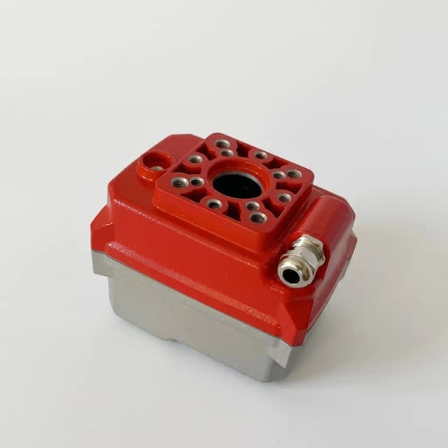
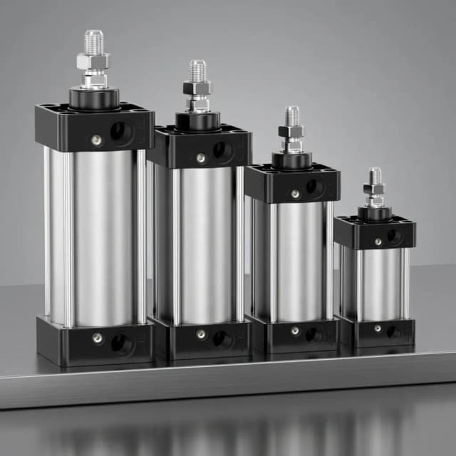
Representative actuator cap machining visuals. Final material, coating, and inspection status are verified from the RFQ package.
Cap Turning Setup
Mill-Turn Port Machining
Finished Actuator Caps
Related Actuator Machining Decisions
Use these adjacent pages when the cap is part of a larger actuator assembly or when the RFQ includes matching bodies, base plates, or long-bore components.
What materials are commonly used for actuator caps?
Aluminum 6061-T6 is common when the drawing leaves enough wall thickness, thread engagement, and fatigue margin. Steel 1045, 4140, or stainless grades are selected when the cap needs more strength, wear margin, corrosion resistance, or coating compatibility. Material choice is a screening input, not a standalone pressure rating.
How do you handle complex porting in actuator caps?
We use CNC mill-turn centers for caps with side ports or angled ports. This allows us to turn the OD, face the cap, bore the center, and mill the ports in a single setup, reducing handling time and improving positional accuracy.
What tolerances can you hold on seal grooves?
Seal-groove tolerances are quoted against the drawing, seal supplier data, and the selected inspection method. ISO 3601-2:2025 and ISO 5597:2018 provide dimensional frameworks for O-ring and rod/piston seal housings, but they do not replace a part-specific tolerance stack.
Do you offer surface treatments like anodizing?
Yes, aluminum caps are often clear or black anodized (MIL-A-8625) for corrosion resistance. For steel caps, we offer zinc plating or nitrocarburizing. We always adjust pre-plating machining tolerances to account for coating thickness.
What information do you need to quote actuator cap machining?
A 2D drawing with critical dimensions, ISO 286 tolerance fits (e.g., H9/f8), seal groove standards (ISO 3601-2), threaded port details, and material specification. A 3D model is highly recommended if the cap has off-axis ports.
Is the routing checker a pressure-rating calculator?
No. It is a manufacturability screen for geometry, material family, and feature complexity. Pressure capacity still requires wall-thickness calculations, fatigue review, thread engagement checks, and the customer-approved seal system.
When does an actuator cap need mill-turn machining?
Mill-turn is usually preferred when a cap combines turned datums with side ports, angled holes, bolt patterns, or threaded features that must stay positionally controlled to the central bore.
How should coating be handled on seal grooves and ports?
The drawing should state whether dimensions are before or after anodizing, plating, nitrocarburizing, or passivation. Coating buildup can close up grooves, reduce thread clearance, or change sealing compression.
How are burrs controlled in cross-drilled ports?
We plan deburring access before quoting the route. Intersecting ports may need in-machine deburring, abrasive-flow deburring, borescope checks, or a customer-defined cleanliness limit for the fluid path.
Which features usually need CMM or surface inspection?
Datum bores, seal grooves, port positions, bolt patterns, face flatness, and dynamic sealing surfaces usually need documented inspection. Surface texture checks should state the parameter, cutoff, instrument method, and acceptance rule.
Can prototype and production actuator caps use the same route?
Sometimes. Prototype routes may use more flexible setups, while production lots often justify dedicated soft jaws, family fixtures, in-process gauging, and a locked inspection plan.
What makes a cap quote inconclusive?
Missing datum schemes, unspecified seal supplier data, unknown coating thickness, unclear port thread standards, and missing pressure/load assumptions all prevent a reliable production route or firm tolerance commitment.