
Actuator Housing Bore Tolerance & Fit Guide
Calculate bore limits, then review fit, finish and inspection.
Reviewed
Decide the function before tightening the tolerance
Specify both parts
A hole class gives bore limits. Combine them with mating-part limits to establish fit.
Separate size and form
A tight size band is not a substitute for form, orientation, datum or texture requirements.
Review service conditions
Thermal and pressure changes modify the fit; the calculator does not approve seals or pressure ratings.
Qualify the measurement
Jet arrangement and sampling determine which defects are visible.
ISO 286 hole limits: size is only half of the fit
H has zero lower hole deviation; the grade sets the size-band width. The tool uses tabulated values with lower-exclusive, upper-inclusive diameter steps. Exactly 3 mm belongs to the up-to-3 row. ISO 286-2:2010 — hole and shaft limit deviations; numeric cross-check: RINGSPANN — Precision Clamping Fixtures, p. 77: basic tolerances.
| Hole class | Lower / upper deviation (µm) | Finished diameter (mm) | Decision to confirm |
|---|---|---|---|
| H6 | 0 / +16 | 50.000–50.016 | Can the function justify the tighter band? |
| H7 | 0 / +25 | 50.000–50.025 | What are the bearing / mating OD limits? |
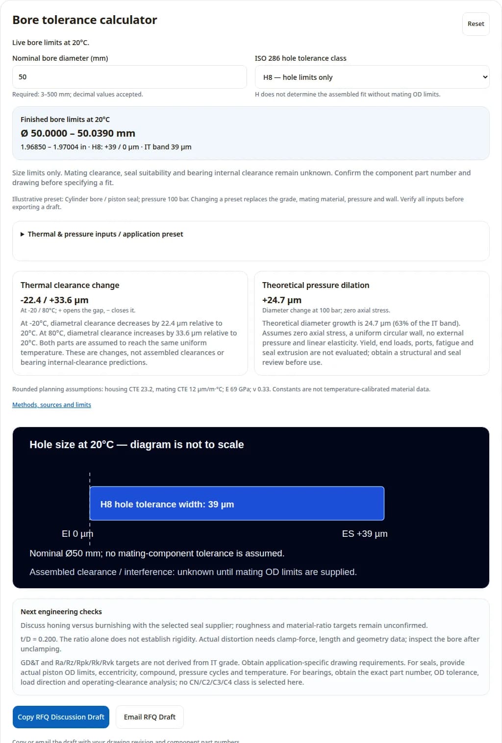
| H8 | 0 / +39 | 50.000–50.039 | Does the chosen seal permit this range? |
| H9 | 0 / +62 | 50.000–50.062 | Is the larger gap compatible with function? |
| H10 | 0 / +100 | 50.000–50.100 | Are clearance and guidance still controlled? |
| H11 | 0 / +160 | 50.000–50.160 | Is a loose bore acceptable for this feature? |
Small screen: swipe or focus the table and use arrow keys to view all columns.
Minimum clearance = smallest bore − largest mating OD. Maximum clearance = largest bore − smallest mating OD. Positive values throughout indicate clearance; negative values throughout indicate interference; a range spanning zero indicates a transition. J7/K7/M7/N7/P7 require exact verified deviations, so the tool offers a drawing-review path instead of estimated limits.
Control form, orientation and inspection explicitly
Size, roundness, cylindricity and runout answer different questions. Identify the governing drawing standard and datum system. A form tolerance derived as a fixed percentage of IT is only a budgeting heuristic; this page does not impose it as an ASME or ISO requirement. ISO 12180-1:2011 — cylindricity vocabulary and parameters.
ISO GPS uses independence unless a specification links characteristics. A specified envelope adds a maximum-material boundary for the regular feature. ASME Rule #1 normally supplies that boundary by default, subject to its exceptions. This comparison is limited to regular cylindrical features; it does not establish interchangeability of a complete assembly. ISO 8015:2011 — GPS fundamentals and independence; ISO 14405-1:2025 — linear size specification operators;ASME Y14.5-2018 (R2024) — dimensioning and tolerancing.
| Drawing basis | Size / form relationship | Remaining decision |
|---|---|---|
| ISO GPS without an envelope | Independent characteristics by default | Define the required size operator and separate form limits |
| ISO GPS with envelope requirement | Maximum-material boundary added to the specified feature | Other form, datum and mating requirements remain |
| ASME Y14.5 Rule #1 | Default envelope for regular features of size, with exceptions | Check exceptions and the governing drawing notes |
Small screen: swipe or focus the table and use arrow keys to view all columns.
| Concern | Requirement to discuss | Inspection / missing decision |
|---|---|---|
| Seal travel | Bore size plus appropriate form and surface texture | Define travel length, sampling and seal specification |
| Bearing seat | Size, seat form and shoulder relationship | Use bearing supplier load and seat guidance |
| Tandem bores | Axis alignment to a stated datum framework | Agree on circular / total runout or other control |
| Motor cavity | Fit and alignment to bearing features | Confirm air-gap budget with motor designer |
Small screen: swipe or focus the table and use arrow keys to view all columns.
Least-squares and minimum-zone algorithms fit different reference cylinders. Least squares does not simply delete peaks: software can evaluate residual extremes. Minimum zone optimizes the enclosing cylinders for the measured points. Neither validates unmeasured surfaces; record filtering, point density, alignment and uncertainty.
Prepare a bore tolerance drawing reviewTemperature changes the clearance, not the ISO size band
The tool uses ΔC = D × (αhousing − αmate) × (T − 20°C). This is an equal-nominal-diameter, common-temperature approximation for unconstrained materials. The representative constants are visible beside the result; they are assumptions, not batch-certified properties or temperature-dependent material curves. ISO 1:2022 — standard reference temperature.
| Assumed CTE pair (µm/m·°C) | At −40°C (µm) | At +80°C (µm) | Interpretation |
|---|---|---|---|
| Al 6061 23.2 / bearing steel 11.9 | −33.9 | +33.9 | Cold tightens; hot opens |
| Steel 4140 12.0 / same steel 12.0 | 0.0 | 0.0 | Matched CTE; gradients can still matter |
| Steel 4140 12.0 / bronze 18.0 | +18.0 | −18.0 | Cold opens; hot tightens |
Small screen: swipe or focus the table and use arrow keys to view all columns.
A 33.9 µm change exceeds the Ø50 H7 band of 25 µm, but it does not by itself prove creep, seizure or bearing preload. Actual initial interference and part temperatures are needed. For rolling bearings, obtain the exact bearing and fit model; this tool does not apply a blanket 80% conversion or choose CN/C3/C4. SKF Rolling Bearings catalogue — bearing interfaces and internal clearance.
Pressure dilation is conditional; seal support remains a separate decision
With Di=50 mm, wall=10 mm, Do=70 mm, E=69,000 MPa, ν=0.33 and P=10 MPa (100 bar), the open-end model gives ΔDi=24.7 µm and bore hoop stress=30.8 MPa. At 210 bar the predicted dilation is 51.9 µm. These are elastic-model calculations, not pressure ratings. University of Western Australia DANotes — thick cylinders.
At the bore, σr=−P and σθ=P(Do²+Di²)/(Do²−Di²). Hooke’s law gives ΔDi=Di(σθ−νσr)/E when σz=0. A closed-end cylinder has an additional axial stress term, so the same formula must not be treated as an exact closed-end actuator result.
| Item | Available here | Next action |
|---|---|---|
| Bore size and pressure change | Conditional diametral estimate | Combine with mating limits and actual restraint model |
| Extrusion gap | Unknown: piston limits / eccentricity absent | Establish worst-case supplier-defined gap |
| Seal backup selection | Unknown: compound / profile / hardness absent | Check exact seal supplier envelope and pressure cycles |
| Elastic validity / allowable stress | Unknown: strength and design criteria absent | Check material at temperature, yield, fatigue and local features |
| Large predicted deformation | Estimate withheld above 1% diameter strain | Use structural analysis; 1% is a numerical cutoff, not a safety limit |
Small screen: swipe or focus the table and use arrow keys to view all columns.
For O-rings, Parker’s extrusion chart specifies test conditions and asks designers to account for cylinder expansion. It cannot establish universal allowable gaps for U-cups or PTFE slipper seals. Parker O-Ring Handbook ORD 5700 — §3.1.4 and Figure 3-2; O-ring housing scope: ISO 3601-2:2025 — O-ring housing dimensions.
Match the texture to the selected contact surface
Parameter definitions: ISO 21920-2:2021 — profile surface-texture parameters. The selected seal specification supplies numerical acceptance limits.
Specify finish by function: a dynamic sealing track, bearing seat and static gland do not share one universal Ra. Plateau honing can be a candidate for a lubricated reciprocating surface; it is not automatically appropriate for every housing material, coating or seal. Ra 0.2–0.4 µm is a discussion example here, not an ISO-mandated range.
| Characteristic | What it helps describe | Requirement still needed |
|---|---|---|
| Ra / Rz | Average profile and height characteristics | Parameter convention, limit, filter and evaluation length |
| Rpk / Rk / Rvk | Reduced peaks, core and valleys on a plateau profile | Supplier-approved limits and measurement method |
| Lay / directional marks | Directional grooves crossing a sealing track | Seal-specific finish guidance and trial validation |
| Coated surface | Final contact topography after treatment | Accepted post-treatment state and thickness |
Small screen: swipe or focus the table and use arrow keys to view all columns.
Do not copy a rotary shaft-seal zero-lead requirement to a reciprocating bore without its actual specification. Texture metrics alone do not prove leak-free operation or a service-life count. Review the chosen seal’s counterface recommendations alongside its installation dimensions. Parker O-Ring Handbook ORD 5700 — §3.1.4 and Figure 3-2.
Measure the released part and match the gage to the defect
Localized clamping loads can alter thin-wall form during machining. Release and remeasure at the drawing’s defined inspection state; compare several angular and axial positions. The wall ratio alone cannot predict a micrometre error or prove that pie jaws achieve a particular Cpk.
Mahr explains that opposed jets can miss odd lobing, while a three-jet circuit has different form sensitivity. Select tooling for the profile and surface finish; correlate it with calibrated masters and a suitable reference method. A three-jet reading is not a direct substitute for full 3D cylindricity. Mahr Millimar Air Gaging catalogue — Applications, p. 12.
| Method | Useful observation | Blind spot / qualification |
|---|---|---|
| Opposed two-point / two-jet gage | Size changes across sampled sections | Some odd lobing can cancel; compare with a form method |
| Three-jet air tooling | Different sensitivity to lobing with suitable circuit and rotation | Does not establish full 3D cylindricity; validate using masters |
| Scanning CMM / form tester | Sampled geometry and form evaluation | Probe, sampling, filters, alignment and uncertainty affect results |
| Texture instrument | Profile parameters at measured tracks | Confirm filter, trace direction and evaluation length |
Small screen: swipe or focus the table and use arrow keys to view all columns.
ISO 14253-1:2017 — measurement uncertainty and conformity decisions addresses uncertainty in conformity decisions. Agree on the decision rule before inspection. In an illustrative symmetric U guard-band rule, accept measured values only within [LSL+U, USL−U]. For Ø40 H6, T=16 µm and assumed U=2.5 µm, the interval is 40.0025–40.0135 mm, leaving 11 µm (68.75%) of the original band. Here U is an assumed expanded uncertainty with a stated coverage choice, not instrument resolution or a generic CMM rating. Actual ISO/contract decision rules and uncertainty evaluation require the applicable clauses and a task-specific uncertainty budget.
Compare process routes by access, finishing state and verification cost
| Candidate route | Useful discussion case | Cost / mismatch risk | Mitigation |
|---|---|---|---|
| Fine boring | Accessible bores with datum relationships | Tool deflection, feed marks and release distortion | Review reach and final form / texture evidence |
| Reaming | Repeated sizes and suitable through access | Tool size dependency; limited correction of upstream errors | Qualify pre-bore and tool condition |
| Honing | Form and texture refinement where access permits | Extra stock, tooling, cleaning and handling | Agree allowance and post-process inspection |
| Roller burnishing | Ductile, accessible surfaces with controlled pre-machining | Can change size and form; texture may not suit the seal | Qualify stock, material, final size and counterface texture |
| ID grinding | Suitable hard surfaces and precision features | Access, heat, abrasive contamination and setup cost | Review material and cleaning requirements |
Small screen: swipe or focus the table and use arrow keys to view all columns.
Ask for an inspection plan and representative trial data at the requested size, depth, wall and material. A process label does not establish capability. Do not buy a tighter IT grade unless the functional stack needs it; request separate pricing for finishing, dedicated masters and reporting.
Define the final coating state before releasing the bore limits
Request a coating and bore inspection reviewGeometry example: if buildup moves each bore surface inward by 25 µm, diameter decreases by 2×25=50 µm. This alone is wider than the Ø50 H7 band. Growth, penetration and variation must be agreed with the actual finisher; no universal hardcoat allowance is assumed.
Compare masking, a qualified thin treatment, or controlled post-treatment finishing against corrosion, wear and dimensional needs. Specify which features are masked, which surfaces contact the seal or bearing, the final measurement state and the acceptance criteria. Changing finish after machining can invalidate an otherwise correct bore.
Worked planning examples — hypothetical, not customer case records
1. Size-only calculation
Assume Ø50 H7 and a mating OD of 49.980–49.990 mm at 20°C. Bore range is 50.000–50.025 mm. Minimum clearance is 10 µm; maximum is 45 µm. This is clearance at reference temperature. Next: compare with the component’s required service gap and form limits.
2. Temperature can reverse the decision
Use example 1, aluminum/steel CTE 23.2/11.9 and equal part temperature. At −40°C, approximate clearance becomes −23.9 to +11.1 µm; at +80°C, +43.9 to +78.9 µm. A room-temperature clearance fit can tighten at cold. Next: review actual component temperatures and interference tolerance.
3. Pressure adds a review requirement
Use a uniform Ø50 mm aluminum bore, 10 mm wall and 100 bar. The open-end model adds 24.7 µm diameter change. With no piston limits or seal data, total extrusion gap and backup selection remain unknown. Next: obtain those limits and the actual end-restraint model before selecting a seal.
Questions engineers and buyers ask before approving the drawing
Size and fit
What tolerance should an actuator housing bore use?
Start with the component function and its supplier drawing. H8 for a cylinder and H7 for a bearing seat are useful discussion examples, not universal requirements. Seal squeeze, bearing ring load, mating limits, coating and service temperature decide the production callout.
What is the tolerance of a 50 mm H7 bore?
At 20°C, the example limits are 50.000 to 50.025 mm: lower deviation 0 and upper deviation +25 µm. Exactly 50 mm uses the over-30-through-50 mm size step. Just above 50 mm, H7 has a 30 µm band.
Is H7 a complete clearance-fit specification?
H7 specifies the hole only. Minimum diametral clearance equals the smallest hole minus the largest mating part; maximum clearance equals the largest hole minus the smallest mating part. Use both components to classify clearance, transition or interference.
Why do J7, K7 and M7 request drawing review?
Their zone positions require verified fundamental deviations for the exact size interval and grade. This tool deliberately withholds unverified non-H limits. Send the hole callout, nominal size and mating-part limits for an ISO 286-2 check.
Does an H8 bore also control cylindricity?
A size callout and a cylindricity requirement address different characteristics. Apply the governing drawing standard, envelope or independence rules, and a separate form requirement when function needs it. There is no universal requirement that cylindricity equal 35% of the IT band.
How do ISO independence and ASME Rule #1 differ?
Under ISO GPS, independence is the default unless a requirement links characteristics. An explicit envelope requirement can constrain a regular feature at maximum material size. ASME Rule #1 normally supplies an envelope for regular features of size, subject to its exceptions. Confirm the governing edition and modifiers; neither approach by itself controls datum alignment or the mating part.
Thermal and pressure
What does a positive thermal clearance change mean?
The bore grows more than the mating part relative to their assumed 20°C sizes, increasing diametral clearance. A negative value tightens the fit. The tool assumes equal nominal diameters, equal uniform temperature and constant representative CTE; it does not calculate the initial assembled gap.
Can this tool select CN, C3 or C4 bearing clearance?
No. Bearing type, actual ring interference, ring and housing stiffness, shaft fit, temperature differences and required operating clearance are missing. Review the bearing manufacturer’s calculation with the exact part number.
Why are dimensions referenced to 20°C?
20°C is the standard dimensional reference temperature under ISO 1. ISO 1:2022 replaced the 2016 edition. Stabilization time and temperature compensation depend on part size, material, environment and required uncertainty; a fixed soak time is not prescribed here.
What pressure-dilation formula does the calculator use?
For zero external gauge pressure and zero axial stress (open ends), ΔDi = P·Di/E × [(Do² + Di²)/(Do² − Di²) + ν]. It returns diametral change. A uniform Ø50 mm bore with 10 mm wall, E=69 GPa and ν=0.33 gives 24.7 µm at 100 bar, conditional on elastic behavior.
Does a small dilation value prove a barrel is pressure-safe?
No. Dilation is not an allowable stress or pressure rating. Material strength at temperature, end loads, ports, grooves, fatigue, stress concentration and the applicable design rules require separate structural review. Large-deformation estimates are withheld at the numerical cutoff described beside the result; that cutoff is not a yield criterion.
When does a seal need a backup ring?
Use the seal supplier’s envelope for the actual compound, hardness, temperature, worst-case gap and pressure cycle. Include hardware expansion and eccentricity. Pressure alone, or dilation as a percentage of the bore IT band, cannot decide this.
Manufacturing and inspection
Is Ra 0.2–0.4 µm mandatory for all actuator bores?
No. That can be an illustrative finish discussion for a selected dynamic sealing surface. Seal family, fluid, speed, material and coating can require a different finish. Agree on parameters, filters, lay direction and evaluation length with the seal supplier.
Why discuss Rpk, Rk and Rvk as well as Ra?
Ra alone does not describe how peaks, core and valleys are distributed. Plateau-surface parameters can help specify running-in and lubricant-retention characteristics. Numerical limits are application-specific and cannot guarantee seal life on their own.
Can a two-point bore gage miss lobing?
Yes. Some odd-lobed profiles can give nearly constant opposed readings. Mahr describes choosing two- or three-jet tooling according to expected form. Full cylindricity also requires axial and circumferential coverage, calibration and an agreed evaluation method.
Does least-squares CMM fitting hide every local peak?
No. Least squares changes the reference cylinder; measured residual extremes can still be reported. Minimum-zone fitting finds the smallest enclosing radial separation for the sampled points. Sampling, filters and uncertainty limit both methods; neither guarantees unmeasured surfaces.
How should coatings be included in bore tolerance?
Specify the final inspection state and agree with the finisher on growth and variation. For example, an assumed 25 µm inward buildup per bore surface reduces diameter by 50 µm. That is a geometric example, not a universal anodizing allowance or masking instruction.
Is a groove-to-seat spacing of 1.5 times wall thickness mandatory?
No general DIN 472 requirement is asserted here. Select the retaining ring and groove using the manufacturer’s load and geometry data, then assess nearby seat distortion and residual wall. Spacing and machining order need review for the actual housing.
What information should accompany a bore machining RFQ?
Include drawing revision, mating limits and component part numbers, material and treatment, final coating state, datum scheme, form and finish requirements, temperature and pressure cases, quantity, inspection reporting and destination. Request capability and certification evidence relevant to the order.
How much tolerance does measurement uncertainty consume?
It depends on the agreed decision rule and the actual measurement uncertainty. In a hypothetical symmetric rule accepting only results from LSL+U to USL−U, a 40 mm H6 bore has a 16 µm band. With assumed expanded uncertainty U=2.5 µm, the acceptance interval is 40.0025–40.0135 mm, 11 µm wide. This is an illustrative rule, not a universal instrument specification or a blanket reading of ISO 14253-1.
Does a 350 bar cylinder automatically require plateau honing?
No. Pressure alone cannot choose a finishing route or Rpk/Rk/Rvk limits. Confirm the seal counterface specification, fluid, speed, material, coating, lubrication and operating cycle; then qualify a process using final-state measurements and an agreed functional trial. Burnishing, honing and grinding have different access, stock and cleaning requirements.
Reproduce the default calculator result
Sources, method and limits
Published by Actuator Machining
Evidence checked November 4, 2026. Catalogue pages establish standard identity and scope; full normative clauses may require licensed access. Public evidence does not establish a universal DIN groove-spacing rule, seal-life guarantee or actuator-specific tolerance recommendation. Illustrative engineering choices are identified as such.
- ISO 286-2:2010 — hole and shaft limit deviations
Catalogue identifies the limit-deviation standard. Consult the licensed tables and applicable corrigendum for production; this tool limits numeric lookup to H6–H11.
- RINGSPANN — Precision Clamping Fixtures, p. 77: basic tolerances
Public manufacturer table used to cross-check IT6–IT11 size steps, including the up-to-3 mm row. It does not select a fit for a particular actuator.
- ISO 1:2022 — standard reference temperature
Current reference-temperature standard, replacing the 2016 edition. Dimensions on this page are referenced to 20°C.
- ISO 12180-1:2011 — cylindricity vocabulary and parameters
Cylindrical form terminology. This catalogue does not impose a universal cylindricity-to-IT ratio or guarantee that a sampled scan finds every surface defect.
- Parker O-Ring Handbook ORD 5700 — §3.1.4 and Figure 3-2
Extrusion review depends on compound, hardness, actual clearance, pressure and hardware breathing. The chart has test conditions; do not transfer it to every dynamic seal family.
- SKF Rolling Bearings catalogue — bearing interfaces and internal clearance
Manufacturer guidance for bearing fits and resulting clearance. Use the exact bearing type, ring load and assembly conditions before selecting a seat or clearance class.
- Mahr Millimar Air Gaging catalogue — Applications, p. 12
Explains two- versus three-jet response to even/odd lobing and the effect of surface finish on air-gage correlation.
- University of Western Australia DANotes — thick cylinders
Lamé stress theory distinguishes open and closed ends. The tool combines the open-end stresses with linear isotropic Hooke’s law to estimate bore diameter change.
- ISO 8015:2011 — GPS fundamentals and independence
Drawing interpretation principles; size and form are independent unless a specification establishes their relationship.
- ISO 14405-1:2025 — linear size specification operators
The 2025 edition replaces 2016. Confirm the edition and size operator on the released drawing; an envelope does not control every aspect of assembly.
- ASME Y14.5-2018 (R2024) — dimensioning and tolerancing
ASME drawing rules, including the default envelope rule for regular features of size and its exceptions; identify the contractually invoked standard.
- ISO 14253-1:2017 — measurement uncertainty and conformity decisions
Conformity decision rules account for measurement uncertainty. The symmetric U guard-band example below is an explicitly assumed decision rule, not a claim that all contracts require k=2.
- ISO 21920-2:2021 — profile surface-texture parameters
Parameter definitions, not universal actuator acceptance limits. The catalogue lists ISO 13565-2:1996 among replaced publications; retain an older edition when required by the drawing.
- ISO 3601-2:2025 — O-ring housing dimensions
Replaces 2016; addresses general O-ring housings, including designs with backup rings. It is not a universal surface-finish or gap specification for every dynamic seal profile.
Method boundaries: synchronous, local calculations; no stored customer data. The model uses constant representative CTE/E/ν, equal nominal diameters and common uniform temperature. Thermal gradients, assembly constraints, coatings and contact stiffness require separate assessment. Pressure output assumes linear elasticity and open ends, and checks neither yielding nor allowable pressure. Published input limits are numerical tool limits, not service ratings.
Responsible publisher: Actuator Machining. Decision boundary: only H6–H11 size limits are calculated. Actual mating clearance, component selection, GD&T, finish and structural approval require the released drawing and supplier data. Created October 21, 2026. Next evidence review by May 4, 2027, or sooner if a cited standard, model or drawing requirement changes. All three examples are hypothetical arithmetic demonstrations; no customer measurements, certification or delivery commitment is implied.
Turn the result into a drawing review
Send the drawing revision, CAD, material/heat treatment, mating limits and component numbers, temperature/pressure/load cases, finish state, quantity and required inspection report. Request applicable capability and certification evidence and confirm lead time with the quotation.
Email [email protected]Attach drawings manually in your email app. The calculator above offers a full discussion draft to copy or email.